Timing Belt Service
The Timing Belt Service (often called the 120k or 60k service) is perhaps the most vital and significant maintenance job for the Z32. Because the VG30DE(TT) is an interference engine, maintaining the timing belt system is essential. Should the timing belt or one of its related components fail, it is extremely likely that major engine components (pistons and valves, specifically) will be destroyed as they collide with one another.
Because of the complexity of this job, it can also be expensive to have it done at a shop. However, it can be performed by a competent shadetree mechanic. But if you're not up to completing this job, just remember, $500 parts and $600 in labor is cheaper than replacing and/or rebuilding the engine.
Images and info presented below are combinations of original work, from rockchucker's many revival threads and TTZD's Writeup.


Contents
- 1 Parts Needed
- 2 60,000 Mile Service
- 3 120,000 Mile Service
- 4 Additional Parts
- 5 Tools Needed
- 6 Procedure
- 7 Radiator & Belts
- 8 Water Pipes
- 9 Crank Pulley
- 10 Timing Belt Covers & Water Pump
- 11 Timing Belt Removal
- 12 Water Pump Installation
- 13 Sprocket Removal
- 14 Rear Timing Belt Covers
- 15 Cam and Seals
- 16 Crank Sprocket and Seal
- 17 Rear Covers & Cam Sprockets
- 18 Idlers and Tensioner
- 19 Setting the Timing Belt
- 20 Tensioning the Belt
- 21 Timing Covers
- 22 Coolant Pipes
- 23 Crank Pulley and Accessory Belts
- 24 Radiator
Parts Needed
There are actually two forms of the Timing Belt service: the 60,000 mile timing belt replacement and the 120,000 mile replacement. The FSM recommends replacing the belt every 60k or 48 months, whichever comes first. Because the related components (like the idler pulleys) are so vital in maintaining engine health, it's highly recommended to just do a complete 120k service instead of the basic 60k. Other components, like the water pump and thermostat, are not necessary to maintaining timing belt functionality obviously. However, replacing these components is most easily performed while the engine is dismantled for the timing belt service, so it's the perfect time to replace them.
60,000 Mile Service
- Timing Belt
- Tensioner
- Water Pump
- Thermostat
- Coolant Bypass Hoses
- Camshaft Seals
- Crankshaft Seal
120,000 Mile Service
- Everything included in the 60,000 Mile Service above.
- Upper Idler Pulley
- Lower Idler Pulley
- Idler Studs
Additional Parts
There are a few optional components often included with either/both of the above kits.
- VTC Springs & O-Rings
- There is much debate circulating the validity in VTC Springs failing. For more information about how VTC works, see the main article. The O-rings should generally be replaced, as you'll need to remove the covers to get the cam gear off, and the O-Rings are usually squished.
- Crank Sprocket Spacers
- These are included with some kits, but often don't need to be replaced unless they're lost or damage.
- Crank Pulley/Sprocket Woodruff Keys
- These don't explicitly need to be replaced, but are often lost during the service.
- Crank Sprocket
- The crank sprocket is often stuck on the crankshaft pretty hard. A common method to remove it is to chisel it off with an air hammer.
- RameyZ Idler Studs
- Some owners have experienced failure of stock idler studs. RameyZ sells heavy duty idler studs to prevent failure.
Finally, it is highly recommended that all parts in this job are replaced with Nissan OEM parts. The only exceptions being the RameyZ idler studs and, optionally, a Gates/GReddy High Strength Timing Belt.
Tools Needed
- Usual assortment of metric sockets and wrenches.
- 27mm socket for crank pulley.
- 5mm and 6mm hex/alan key sockets.
- A fish scale (or push-pull gauge) helps tremendously with setting the belt.
- Pulley pullers
- Plastic faced mallet
- Thin strip of lexan/plastic
- Pry bar
- Seal puller (optional)
- Impact tools (optional; highly recommended for automatic transmission vehicles)
Procedure
Radiator & Belts
Radiator
- Jack up and support the front of the vehicle if necessary to remove shields and fit a radiator drain pan underneath.
- Drain coolant from radiator. Don't forget to remove the radiator cap to allow all the coolant to escape
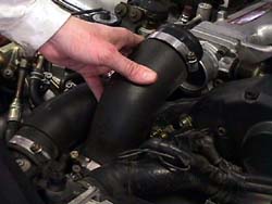
- For Twin Turbo models, remove the throttle body intake hoses/pipes. Be sure to block the intercooler outlets with rags to prevent foreign debris from falling in.
- If your PTU is still in the stock location, remove it and clip the zip ties holding the harness to the upper water pipe.
- Remove the upper radiator hose.
- Remove the lower radiator hose.
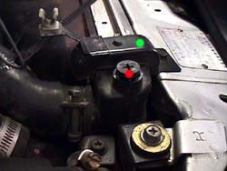
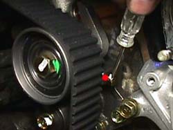
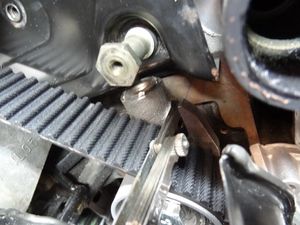
- Remove 2x 10mm bolts securing the upper radiator brackets to the chassis (green dot).
- Remove the lower radiator shroud (3 clips).
- Remove the radiator from the vehicle. On TT models, you'll have to wiggle it a bit to clear the intercooler piping.
- Don't loose the little rubber insulators that the radiator sits in!


Belts
- Remove the 4x 10mm bolts securing the fan clutch to the water pump pulley.
- Carefully remove the fan clutch. There will be tension on the belt, so the pulley will try to move a bit, but it shouldn't pop off.
- Loosen the lock nut (12mm on the tensioner arm) and lock nut (14mm through the pulley holes) on the power steering pump.
- The PS pump can be tough to move. You may also have to loosen the 2x 12mm bolts securing the bracket to the block.
- You may have to use a pry bar to move the power steering pump inward.
- Loosen the power steering pump tensioner adjustment 12mm bolt, pushing the pump inward as you go along, to relieve tension on the belt.
- Loosen the lock nut (12mm on the tensioner) of the A/C tensioner, which is just below the A/C compressor.
- Loosen the A/C compressor tensioner adjustment bolt (accessible from the underside) to relieve tension on the belt.
- Loosen the lock nut (12mm on the tensioner) of the alternator adjustment bracket.
- Loosen the 12mm adjustment bolt on the alternator tensioner to relieve tension on the belt.
- Remove all three accessory belts.
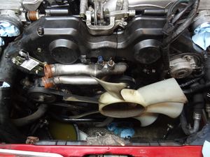
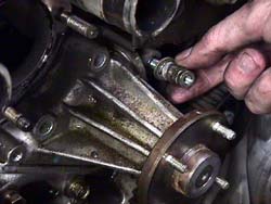
Water Pipes
- If you have not already done so, remove the PTU from it's stock location.
- Disconnect both coolant temperature sensors, and pull the harness away from the pipes completely.
- Move your coolant bucket to the front of the engine.
- Remove the lower coolant pipe (2x 12mm nuts, 1x 6mm hex head).
- Use some long pliers to squeeze the clamps on the coolant bypass tubes and move them towards the engine, off the upper coolant pipe.
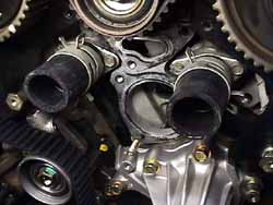
- Remove the upper coolant pipe (3x 6mm hex heads).
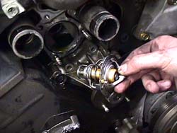
- Remove the thermostat from its housing.
- Completely remove the coolant bypass hoses.


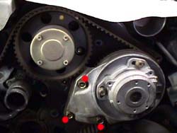
Crank Pulley
The Crank Pulley can be a little tough to remove, but of course it's not impossible.

Manual Transmission
- If the vehicle is in the air, lower it so all four wheels are resting on the ground.
- Put the transmission in 5th gear and set the parking brake hard.
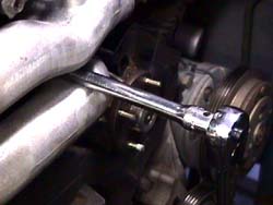
- Loosen the 27mm bolt securing the crank pulley to the crank shaft.
- If you have a breaker bar or a low-profile impact wrench, now is the time to use it.
- Don't fully remove the bolt, as your pulley puller will need to press against it.
Automatic Transmission
- If you have a low-profile impact wrench, use that to loosen the 27mm bolt securing the crank pulley to the crank shaft. You can then skip to the next section.
- Otherwise, remove the starter motor and use a screwdriver or flywheel stop tool to prevent the flex plate from rotating.
- Loosen the 27mm bolt securing the crank pulley to the crank shaft.
Pulley Removal
Once you have the pulley's bolt loosened, you can remove the pulley itself.

- Attach a jaw puller to the crank pulley, so the jaw is grasping the large part of the pulley (not the front part). Let the dimple in the bolt be the resting spot for the jaw puller's drive bolt.
- Slowly tighten the jaw puller's drive bolt the draw the pulley off the crankshaft.
- Periodically relieve tension on the pulley before pulling on it more. It is made of two pieces with a rubber coupler to dampen vibration, and pulling it off in one shot can damage or even separate the rubber coupler.
Alternatively, you can use a threaded puller (ie a steering wheel puller) to remove the pulley, as it has two threaded holes in the front.
Be careful not to drop the pulley. It's a friggin' boat anchor!
Timing Belt Covers & Water Pump
- Remove the driver's side timing belt cover (3x 8mm Philips, 5x 5mm hex bolts). They are a variety of different lengths and styles, so try to keep them in order!
- Remove the passenger's side timing belt cover (2x 8mm Philips, 5x 5mm hex bolts). They are a variety of different lengths and styles, so try to keep them in order.
- Remove the lower timing belt cover (6x 8mm Philips).
- If they didn't come off with the upper covers, remove the spacer studs (2x 17mm).
- Remove the water pump (6x 12mm).

Timing Belt Removal
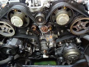
Now that you have easy access to all the timing components, we can get into the nitty gritty.
- Re-install the crank pulley bolt by hand so you can use the 27mm socket + a ratchet to rotate the engine. You will only be able to rotate the engine clockwise.
- Put the transmission in neutral. Rotate the engine (via the crank bolt) clockwise until the dimples on the crank sprockets align with the dimples on the rear timing belt covers, and the line on crank pulley aligns with 0 degrees.
- The sprocket marks will not align perfectly; these dimples are for reference at this step only. This is simply to get the engine approximately at top dead center.
- If you set the engine at approximately 10 degrees BEFORE top fead center (BTDC), it will leave the cams in a slightly more neutral position, so they will be less likely to recoil to one side when the belt is removed.
- Take a 10mm bolt from the fan and thread it into the tab on the auto tensioner. As you tighten it, it will compress the piston and relieve tension from the belt. Insert it just enough to begin relieving tension on the belt; you don't want to fully loosen the belt with this.
- Tighten this bolt VERY SLOWLY. If you go too fast, it will break that tab off like it wasn't even there.
- There are two bolts with a nut between them securing the tensioner to the block. Start by loosening the two bolts, then very slowly loosen the nut in the center. As it loosens, the tensioner will shift and the belt will lose it's tension.
- Remove the auto-tensioner.
- Carefully remove the belt. The sprockets may try to violently snap to either position, but as long as the engine is set near TDC (as it should be), no damage should be incurred.
- Remove the upper and lower idler pulleys (1x 12mm nut on each one).
Water Pump Installation
- Clean up the mating surface for the water pump. Be careful not to gouge the mating surface; a little wire brush will clean it right up without doing any damage.
- Double-nut the new water pump studs into place on the pulley mount. Use a bit of thread locker to prevent them from backing out.
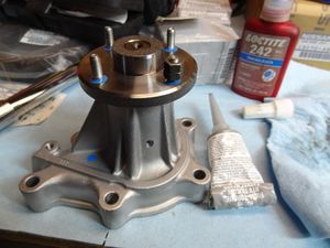
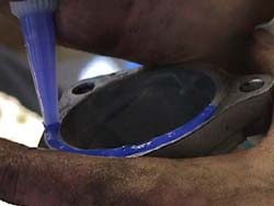
- Apply a thin bead of gasket maket to the slot in the new water pump.
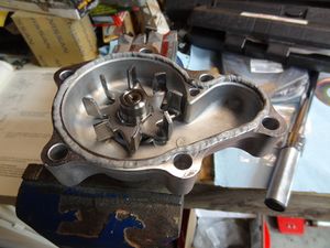
- Install the new water pump (6x 12mm). The "stud" goes in the furthest right hole.
- Tighten bolts to 12-15 ft-lbs.


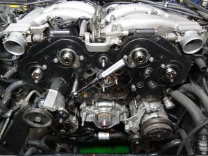
Sprocket Removal
The following steps will require you use the old timing belt to secure the position of the cam gears while you loosen the bolts. Everyone has their own way of doing this, but pictures of some recommended ways are provided.
Intake Cams
|
|
|
| Passenger Side |
Driver Side |


- Remove the bolts securing the VTC cover to the intake cam gears (4x Philips, 7mm)
- Remove these slowly and carefully, as there will be a spring behind them desperately trying to escape.
- Be sure not to lose the O-rings, though they should be replaced anyways.
- Remove the bolt securing the gear to the cam (1x 19mm). You can use the belt-wrap technique to hold the gear in place while you remove it.
- Remove the gear.
- Repeat for the opposite side.

Exhaust Cams
|
|
|
| Passenger Side |
Driver Side |


- Remove the CAS from it's bracket (3x 10mm). Feel free to mark its position to make reinstallation a bit smoother.
- Don't leave the CAS attached to its bracket and remove the bracket. The bracket often comes out in an awkward jerking motion, and this can break the alignment pin on the CAS or the exhaust cam. Further, installing the CAS is a lot easier when it's not attached to the bracket, since you have more freedom of movement to line it up.
- Remove the CAS bracket from the head (3x 12mm).
- Remove the bolts securing the sprocket to the cam (4x 11mm). You can use the belt-wrap technique to hold the gear in place while you loosen the bolts.
- Remove the sprocket.
- Repeat for the opposite side.

Rear Timing Belt Covers
- If you have not already done so, remove the two studs on the rear timing belt covers (2x 17mm)
- If you have not already done so, remove the two idlers (2x 14mm)
- Remove the two idler studs if they are to be replaced (highly recommended). If necessary, this can be done by doubling up two nuts onto each stud, tightening them against each other, and then using the inner one to remove the stud.
- Remove the passenger side rear timing belt cover (4x 10mm).
- Remove the driver's side rear timing belt cover (4x 10mm).
Cam and Seals
Removal
- Remove the cam seals by carefully prying them with a punch of small flathead.
- Lightly tap the tool into the area between the cam seal and the housing/head.
- Gently pry out a bit, then pull the tool out and move it over to a different spot on the cam seal.
- Work your way around the cam seal until it breaks free.
- Be extremely careful not to scratch the cam. Doing so will result in a leak that is NOT easy to repair. Use the utmost caution and be extremely careful when pulling the seals.
- Repeat these steps for all four cam seals.

Installation
- Apply a bit of oil to the new seals.
- Put the new seals into position and gently push them into place.
- To get them to seat all the way, take one of the old seals and "stack it" against the new seal. Use a plastic-headed mallet to tap the new seal into place.
- It will fully seat into place and the face of it should be approximately flush with its housing.

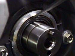
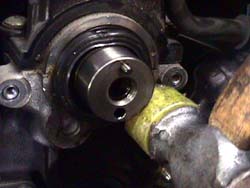
Crank Sprocket and Seal
Removal

- Remove the crank sprocket washer if it's still on.
- Try to pull the crank sprocket off
- You can try to pry it off, but don't put pressure against the oil pump. The oil pump housing is very thin cast aluminum and it WILL crack and put you in a world of pain.
- If you can't directly pull the sprocket off, you'll have to cut it off. Use an air chisel and "aim" for the woodruff key.
- Try to avoid letting the chisel reach the crankshaft itself, you don't want it to damage anything but the crank sprocket.
- Once the sprocket is split, hammer a chisel into the slot to spread it open a bit. It will then come off pretty easily.
- Remove the woodruff key if it's damaged.
- Remove the rear timing belt washer.
- Remove the crank seal in the same manner the cam seals are removed. It's a little more difficult to remove because of its position and proximity to the oil pump, but the idea is the same.
- DO NOT scratch the crankshaft. Fuck you if you do.
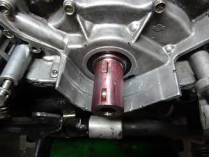
Installation
- The crank seal is a bit more difficult to install than the cam seals, because there's a lip on the crankshaft that it needs to go over.
- The best solution to this is to use a thin piece of lexan or plastic, approximately 4.5" x 3". Wrap it around the crankshaft to create a ramp for the seal.
- Apply some oil to the plastic "ramp" and slide the seal into position.
- Like the cam seals, you can double it up with the old seal (even a cam seal; they're the same part) and tap it in. It may help to use a piece of wood due to its proximity to the oil pump.
- Make sure the seal is evenly inserted all the way around (you may have to use an inspection mirror to make sure).
- Remove the plastic ramp.
- Install the washer & the crank sprocket over the woodruff keys on the crank shaft. The flat washer goes on the back side of the sprocket. If the lower belt cover loops around the crank, then a second flat washer goes on the front of the sprocket. If the lower belt cover doesn't loop around the crank, the bevel edged washer goes on the front with the bevel facing the rear to make the belt fall back onto the sprocket if it were to come forward.
- Install a new woodruff key if necessary. Use some pliers to squeeze it into it's slot-- lube doesn't hurt, and use a thick cloth to prevent the pliers from damaging the crank. If possible, set the woodruff key at a slight incline to aide with installation of the crank sprocket.
-
- Slide the sprocket into place. You may have to tap it on over the woodruff key, but only do so once you've verified that it's properly aligned on the key.

Rear Covers & Cam Sprockets
- Install the driver side rear timing belt cover (4x 10mm)
- Install the passenger side rear timing belt cover (4x 10mm)

Cam Sprockets
- Install the exhaust cam sprockets onto the camshafts.
- Tighten the exhaust cam sprocket bolts (8x 11mm). Torque to 10-14 ft-lbs. Use the belt-wrap technique as necessary.
- Be sure the mating surfaces are clean and install the intake cam sprockets.
- Tighten the intake cam bolts (2x 19mm) to 90-95 ft-lbs. Use the belt-wrap technique as necessary.
- Install the VTC Springs, VTC O-Rings (which should be replaced at this time), and covers.
- Apply a small amount of oil to the O-Rings during installation.
- Tighten VTC cover screws (8x Philips, 7mm) to a slight but significant 1.1 to 1.8 ft-lbs.

Idlers and Tensioner
Idlers
- If you're replacing the tensioner studs (again, highly recommended), go ahead and install the new studs now. You can use the same double-nut method if necessary.
- Install the new upper and lower idlers.
- Tighten the idler nuts to 32-43 ft-lbs.
Tensioner
- Verify that the gap of the tensioner is at 4mm. If not, use a vice to close the gap, then install the stopper bolt to prevent it from opening up.
- If a vice is not available, the gap can be closed/opened by VERY SLOWLY turning the stopper bolt. If you do it too fast, it WILL break off the stopper bolt's tab.
- Install the tensioner on the stud and tighten the nut slightly by hand.

Setting the Timing Belt
It is of the utmost importance that the timing belt is installed correctly. It is absolutely essential in the performance and longevity of the engine, so please pay careful attention to these steps.
- Start positioning the belt marks on the appropriate sprocket teeth beginning with the crank sprocket. Stick a screwdriver/pry bar between the belt & the oil pump shielding to hold the belt in place. Pull the belt and line the marks on the exhaust cam sprocket up on the driver's side, then the intake cam sprocket next to it & so on. If the sprockets are not close to the right area to land the marks on, wrap the old timing belt around the sprocket and rotate it until it's close enough to 'capture' under the mark. The dots on the back metal covers are for reference only at this point, same with the notch in the oil pump. All 15 indications will never line up perfectly. The only thing that matters are the lines on the belt and the marks on the sprockets lining up properly.
- The dotted line on the belt lines up at the passenger side exhaust cam.
- Remember, the most important thing is that the lines on the belt correctly line up with the marks on the cam gears. The dimples on the rear timing belt covers are for vague reference ONLY.

|
|
|
|
|
|
| Passenger Exhaust |
Passenger Intake |
Driver Intake |
Driver Exhaust |
Crankshaft |


Click images for full-size views. Will open in a new window or tab.
Tensioning the Belt
- Use a pry bar to push the tensioner inwards so you can get the two outer bolts started.
- Tighten those two bolts slightly by hand.
- Use your prybar to put tension on the belt, but not too tight--just to keep it from slipping.
- Rotate the timing belt clockwise approximately 10 degrees while holding tension on the belt. A helper is a good idea here.
- Tighten tensioner bolts and nut to 12-15 ft-lbs.
- Turn crankshaft counterclockwise 120 degrees (removing the spark plugs helps with this if possible).
- Turn crankshaft clockwise and set cylinder 1 to TDC (the marks on the cam sprockets should approximately line up with those on the rear timing belt covers.
- Loosen nut and bolts.
- Push the end of the tensioner piston with approximately 15.2 to 18.3 lbs of force.
- Tighten nut and bolts to 12-15 ft-lbs.
- Turn crankshaft 120 degrees clockwise.
- Turn crankshaft 120 degrees counter-clockwise.
- Remove the tensioner stopper bolt.
- After 5 minutes, check the gap in the tensioner. It should be between 3.5mm to 5.2mm.
- Rotate the engine at least 720 degrees (two times) to ensure it rotates and the gap on the tensioner does not change.

Timing Covers
Lower
- Install the lower timing belt cover.
- Snug the bolts down (6x 8mm). The short bolt goes in the top hole on the right side.
Passenger Side
- Install the spacer stud (17mm)
- Install the passenger timing belt cover
- Snug the bolts down (2x Philips/8 mm, 5x 5 mm hex head, the lower middle is shorter bolt).
Driver Side
- Install the crank angle sensor bracket. Tighten bolts to 12-15 ft-lbs.
- Install the crank angle sensor, aligning it to your markings early. Tighten bolts to 10-12 ft-lbs.
- Install spacer stud (17mm)
- Install the driver's side timing belt cover.
- Snug the bolts down (3x Pillips/8 mm, 5x 5 mm hex head)
Coolant Pipes
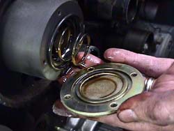
Thermostat
- Place the new thermostat into position. It should sit with the rim of it flush with the mating surface.
- The jiggle valve should be at the top (12 'o clock position).
- Apply a thin bead of gasket maker to the mating surface of the lower coolant pipe.
- Install the lower coolant pipe.
- Tighten nut and bolts (2x 12mm, 1x 6mm hex) to 12-15 ft-lbs.

Lower Coolant Pipe
- Clean the mating surfaces for both upper and lower coolant pipes. Be careful not to scratch the surfaces; just use a wire brush to remove the old gasket.
- If you're replacing the coolant bypass hose mounting pipes, you will also have to clean off their mating surfaces.
- Install the new pipes with a thin bead of gasket maker.
- Bolts should be made snug, but do not need to be exessively tight. Remember that they're going into aluminum.
- Install the two new coolant bypass hoses. Clamp the engine side on fully.
- Install the front clamps for the coolant bypass hoses, but push them back so the water pipe can be inserted.
- Apply a thin bead of gasket maker to the upper coolant pipe's mating surface.
- Install the upper coolant pipe.
- Torque bolts to 12-15 ft-lbs.
- Place clamps into position. Make the left one point down, and the right one point to the bottom-right.


Crank Pulley and Accessory Belts
Crank Pulley
- If you have not already done so, install the front timing belt washer. The rounded side should face the belt, to help guide it into place should it try to wander.
- Insure that the woodruff key is in place.
- Install the crank pulley, being careful to line up the slot for the woodruff key carefully.
- Tighten the bolt down.
- You will need to lock the engine in place, as you did to remove the crank pulley.
- Tighten crank bolt and torque to 159-174 ft-lbs.
Alternator Belt
- Set the water pump pulley onto the pump. Install the bolts and slightly tighten them by hand.
- Install the alternator/water pump belt.
- Tighten the alternator adjustment bolt (12mm) until belt is sufficiently tight. There should be approximately 1/4" of deflection at the mid point.
- Tighten the 12mm lock nut on the adjustment bracket to 20-24 ft-lbs.
- If you had to loosen it, tighten the pivot bolt to 12-15 ft-lbs.
A/C Belt
- Install the A/C belt.
- Tighten the A/C adjustment/idler bolt (12mm) until the belt is sufficiently tight. There should be approximately 1/4" of defletion at the mid point of the belt.
- Tighten the 12mm lock nut on the adjustment bracket to 23 ft-lbs.
Power Steering Belt
- Install the power steering belt.
- Sometimes the power steering pump won't flex itself to adjust enough. In this case, it's sometimes easier to walk the belt on by rotating the crank.
- Tighten the power steering pump adjustment bolt (12mm) until the belt is sufficiently tight. There should be approximately 1/2" of deflection at the mid point of the belt.
- Tighten the 12mm bracket if you loosened it earlier 12-25 ft-lbs.
- Tighten the 12mm lock nut to 12-25 ft-lbs.
- Tighten the 17mm lock nut to approximately 20-24 ft-lbs.
Finally, install the fan clutch. Tighten the nuts down to 4.3-7.2 ft-lbs.
Radiator
- Install the radiator. On a TT model, it can be kind of difficult to get it in because of the intercooler piping.
- Be sure to land the radiator into the little rubber insulators.
- Install the upper and lower coolant hoses.
- Install lower radiator shroud (3 clips).
- Remove rags from intercooler outlet pipes and reinstall throttle body hoses.
- Fill the radiator with coolant bleed the cooling system.
- If you still can, raise the front of the vehicle up to assist in getting coolant into the engine.
- Start the car and allow it to warm up with the heater on.
- Continue to add coolant as the car warms up, revving it slightly as you fill it until it's full.

Confirm there are no leaks, strange squeaks or rattles, etc.... and enjoy!