Variable Timing Control
Variable Timing Control (VTC, sometimes called Variable Cam Timing (VCT), or NVCS (Nissan Variable [timing] Control System or Nissan Variable Cam System) was the name given to the variable cam phasing system featured on the VG30DE(TT) and other similar engines from the era. While similar in application, it is functionally very different and should not be confused with Honda's VTEC system, which was introduced around the same time.
Contents
Function
Variable Timing Control was, at least in the case of the VG30DE, used only on the intake cams. Interestingly, the exhaust side of the head features a cutout that would otherwise appear to accommodate a VTC solenoid. It was a relatively simple (yet mind-bendingly impressive, from an engineering standpoint) solution to a common problem that faces engine designers: timing the cams for good low-end torque or high-end power. Most engines compromise somewhere in the middle, but VTC allowed Nissan to have it's cake and eat it, too.
In short, the VTC system allowed the ECU to advance the cam phasing on the intake cams, depending on different engine situations. This allowed the VG30DE to maintain good low-end torque and smoothness, without sacrificing top-end power.
ECU Control
The ECU controls the VTC mechanisms through the two solenoids, mounted on the back of each head (see "VTC Solenoid" below). The NA and TT ECUs use different parameters to control the VTC function.
Non-Turbo
For the VTC to turn on, the following conditions must be true:
- Temperature between -58°F and 230°F.
- Vehicle speed 6 MPH or higher (0 MPH on some earlier ECUs)
Then, the ECU will enable the VTC if the RPM is between 1800 RPM and 5800 RPM. If the RPM is below the range, it will enable as soon as the TP (the calculated engine load) is above 39ms.

Twin Turbo
For the VTC to turn on, the following conditions must be true:
- Temperature between -49°F and 230°F.
- Vehicle speed 6 MPH or higher (0 MPH on some earlier ECUs)
Then, the ECU will enable the VTC when the TP (calculated engine load) is above 23ms. The VTC is cut (disabled) at 5900 RPM. The TT ECU still has a parameter to enable VTC by RPM alone, but it is set at 6100 RPM, above the 5900 RPM VTC cut. Because of this, it is essentially ignored. The TT's VTC is enabled by TP and disabled by RPM.

Components
The VTC System was made up of three major components:
Camshaft
Main Article: Camshaft
The Intake Cams feature a ball-spring check valve at the back of the camshaft and a hollow oil passageway throughout, with an opening towards the front. The oil passageway allows oil to enter the cam near the front, and either drain back out at the rear (VTC off) or pressurize the helical piston assembly inside the cam gear (VTC On).
VTC Solenoid

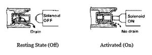
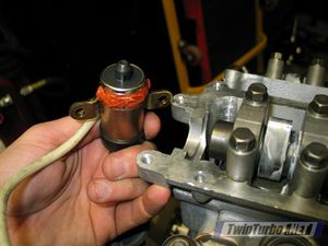
The VTC solenoid (illustrated above and pictured at the beginning of this article) is a solenoid valve mounted to the back of the head, directly behind the intake camshaft. In it's "resting state" (off), it allows oil which had entered the front of the camshaft to drain back out through the rear. Once activated, the VTC solenoid "plunger" presses on a check-valve at the rear of the cam, effectively blocking the flow of oil from leaving the cam through the rear. This forces oil to pressurize the front chamber in the VTC gear at the front of the cam.
VTC Gear
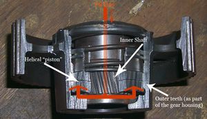
The intake gears on equipped Zs (all but USDM 1996 models) featured an internal helical piston assembly. It was made up of three basic components:
- The main gear, which actually comes into contact with the timing belt. The inside of the gear housing had helical teeth all the way around the inside of it.
- The Inner Shaft. This part connects directly to the camshaft and has a helical teeth all the way around the outside of it.
- The Helical "piston". This part was a sort of metal "ring" with helical teeth on the inside and outside of it. This went between the two halves.
When the VTC Solenoid is activated, it allows oil to flow into the front of the gear and pressurize. This pushes the helical piston back (towards the engine). Because the piston links the inner shaft and outer housing via helical teeth, the movement towards the engine causes the inner shaft (and thus, the camshaft) to rotate the camshaft about 20 degrees clockwise (advanced).=
Problems
As with any complex system, the VTC system has a couple of common problems that tend to materialize on our 20-year-old Datsuns.
- VTC rattle (or tick, knock). There are a few different theories as to why this happens, but the common understanding is it has to do with the helical piston slapping back and forth inside the housing. This is not uncommon in high-mileage engines, but will no doubt begin happening (even with new gears) on engines with heavier valve springs.
- Leakage. In a VTC gear that has begun to fail (usually exhibiting the rattle/knocking noise), the rear/inner shaft becomes "broken" from the gear housing. These two components are pressed together from the factory. When this happens, oil can leak from the rear of the VTC gear.
- Spring fatigue. A common perceived failure is that the small spring at the front of the gear becomes fatigued, allowing the piston to slap around, causing the VTC rattle noise. It is now understood that these springs practically never wear out. While JWT makes "heavy duty" VTC springs, this is essentially a "band-aid" fix for the gear assembly itself wearing out in some manner, and owners who replace their VTC springs with JWT HD springs virtually unanimously report the noise returning shortly thereafter. Some claim that the JWT HD springs actually hinder performance by essentially locking the VTC mechanism.
Further Reading
EF&EC Pages 29 and 30 (link) contains further description regarding the function of the VTC system.

