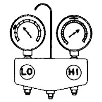
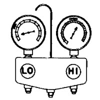
AC Manifold Gauges
Revision as of 21:55, 5 April 2018 by Maintenance script (talk | contribs) (Imported from text file)
Manifold Gauges are a tool commonly used in servicing air conditioning systems. They can be rented or purchased at many auto parts and tools stores.
Contents
Connecting & Use
Setting manifold gauges is simple and straightforward.
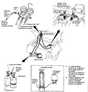
- The low-pressure hose (usually blue) connects to the low pressure service port on the car. This is the larger pipe (see the Air Conditioning System page to see where this is on your car).
- The high pressure hose (usually red) connects to the high pressure service port on the car (next to the passenger side shock tower).
- The center connector (usually yellow) connects to a vacuum pump.
- The low-pressure service connector (usually green) connects to the refrigerant source. The port for this is usually next to the low-pressure gauge on the manifold gauge assembly.
Vacuuming
It is necessary to vacuum the system before charging.
Initial Vacuum
- Completely tighten all fittings and adapter valves.
- Open the high and low pressure valves on the manifold gauge assembly.
- Open the vacuum port (center valve) on the manifold gauge assembly.
- Run the vacuum pump.
- Perform evacuation for more than five minutes to stabilize the vacuum in the system. Check to ensure the low pressure gauge indicates -29.13 to -29.92 inHg.
- Shut off the high and low pressure valves and vacuum valve.
- Shut off the vacuum pump.
Checking for Air Tightness
After performing the above...
- Leave the system as-is for 5 to 10 minutes.
- Make sure the needle of the low-pressure gauge does not move towards the atmospheric (gauge pressure 0) side at all.
- If any reverse movement is noted, it indicates poor system airtighteness. Service the system until airtightness is complete. If pressure changes approx 3.94 inHg in 10 minutes, the refrigerant in the system will be exhausted in about one month.
- Once the system is air tight, continue to fully evacuate the system.
Final Evacuation
Once the system is completely holding vacuum...
- Run vacuum pump.
- Open the high and low pressure valves on the manifold gauge assembly.
- Open the vacuum valve on the manifold gauge assembly.
- Continue to run for more than 20 minutes.
- Close high and low pressure valves and vacuum valve on manifold gauge assembly.
- Continue to the A/C Recharge article.
Reading Manifold Gauges
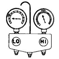
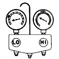
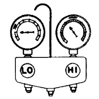
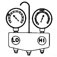
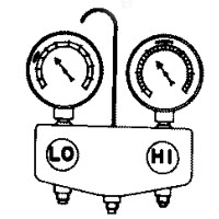
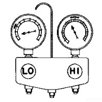
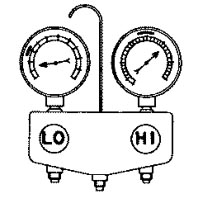
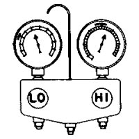
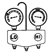
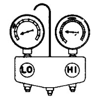
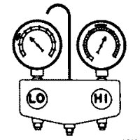
Reading manifold gauges can be a very effective way to quickly and correctly identify issues with the cooling system.
| Condition |
Probable Cause |
Corrective Action | |
|---|---|---|---|
| Insufficient refrigerant charge. Bubbles appear in sigh glass. |
Refrigerant is low; system is slightly leaky. |
| |
| No cooling action. A lot of bubbles or something like mist appears in sight glass. |
Serious refrigerant leak. |
Stop compressor immediately.
| |
| Slight cooling. Sweat or frosting on expansion valve inlet. |
Expansion valve restricts refrigerant flow.
|
If valve reveals sweat or frost:
| |
| Insufficient cooling. Sweat on suction line. |
Expansion valve allows too much refrigerant through evaporator. |
Check valve for operation. If suction side does not show a pressure decrease, replace valve. | |
| No cooling. Sweat or frosting on suction line. |
Malfunctioning expansion valve. |
| |
| Insufficient cooling. Frosted evaporator. |
Suction throttle valve is inoperative. |
| |
| Insufficient cooling. |
Suction throttle valve restricts refrigerant flow. |
| |
| No cooling action; engine may overheat. Bubbles appear in sight glass. Suction line is very hot. |
Usually a malfunctioning/dirty condenser. |
| |
| Insufficient cooling. Frosted high-pressure liquid line. |
Receiver/drier clogged, or restriction in |
| |
| Insufficient cooling. |
Internal problem in compressor, or damaged gasket and valve. |
| |
| Insufficient cooling. |
Too much oil circulates with refrigerant, causing the cooling capacity of the system to be reduced. |
Refer to the Oil Levels Compressor Oil section | |
| Insufficient cooling. Sight glass shows occasional bubbles. |
Air mixed with refrigerant system. |
| |
| After short operation, suction side may show vacuum reading. During this condition, discharge air will be warm. As a warning of this, the reading vibrates around 6 PSI. |
Drier is saturated with moisture. Moisture has frozen in expansion valve. Refrigerant flow is restricted. |
| |
