Auxiliary Fan
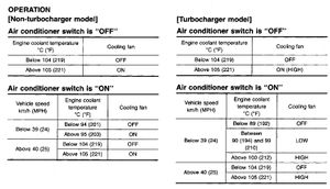
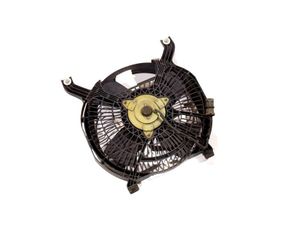
The auxiliary cooling fan is an electric fan mounted in front of the AC condenser. It is operated automatically by the ECU under certain conditions. Under normal driving conditions, the fan will turn on should the car begin to overheat. With the air conditioning turned on, the fan activates at a lower temperature to provide better airflow through the AC condenser.
The NA uses a single-speed fan, and the TT uses a 2-speed fan.
Operating Conditions
The cooling fan operates at different times depending on several conditions, as defined by the Factory Service Manual.

ECU Control
The ECU control for the auxiliary fan is somewhat complicated and relies on input from the speed sensor and coolant temp sensor.
Normal Operation
Thanks to Eric over at the Nissan ECU Tuning Forums for the bulk of this information.
The ECU uses four main sources of information to determine the fan operation.
| Address |
Function |
Stock Value(s) |
|---|---|---|
| 0x7443 |
Base activation temperature w/ AC off. |
8C (140°C) |
| 0x7442 |
Base activation temperature w/ AC on. |
8C (140°C) |
| 0x77ED |
3-byte table defining activation behavior in relation to vehicle speed, with AC off. |
00:00:00 |
| 0x77F0 |
3-byte table defining activation behavior in relation to vehicle speed, with AC on. |
D4:D4:00 |
The A/C operation (on or off) determines which 3-byte table is referenced. From there, the ECU selects one of the three bytes depending on the vehicle speed.
- The first byte is used for vehicle speeds under 20km/h.
- The second byte is used for vehicle speeds between 20km/h and 40km/h.
- The third byte is used for vehicle speeds over 40km/h.
When a byte is selected, it's read by the ECU in binary. This essentially breaks it up into four values of 2-bit data.
For example, let's assume the byte D4 is selected. D4 in binary is 11 01 01 00. These bits are interpreted as:
- 11: Fan on high speed.
- 01: Fan on low speed.
- 00: Fan off.
Finally, each of these bits are referenced depending on a specific temperature. This temperature is based on the "base activation temperature" shown in the table above.
Remember that binary is read right-to-left, so in the example D4 (11 01 01 00), 00 would be the first value. The second value is 01, the third value is 01, and the forth value is 11. That said, these bits are referenced using the table below.
| Value |
Utilized When |
Stock Example |
|---|---|---|
| 1st Pair |
Temperature < ([7442 or 7443] - 50) |
Temp < 90°C |
| 2nd Pair |
Temperature ≥ ([7442 or 7443] - 50) |
Temp ≥ 90°C |
| 3rd Pair |
Temperature ≥ ([7442 or 7443] - 45) |
Temp ≥ 95°C |
| 4th Pair |
Temperature ≥ ([7442 or 7443] - 40) |
Temp ≥ 100°C |
For a final example, let's imagine the car is slowly moving (25km/h) with the A/C on and the coolant temperature is 200°F, or about 93°C.
- Because the AC is on, the ECU will reference the 3-byte table at 0x77F0. The values at this table are D4:D4:00
- The car is moving at 25km/h, so the ECU will reference the second byte of the table (D4).
- D4 in binary translates to 11 01 01 00.
- The ECU determines which pair of bits to use based on the table we see above.
- Temperature of 93°C ≥ ([7442] - 50)
- Temperature of 93°C ≥ (140 - 50)
- Temperature of 93°C ≥ 90.
- Because the calculated condition for the 2nd pair of bits is true, the 2nd pair of bits is used to control the fan.
- The value of the 2nd pair of bits equals 01, which activates the cooling fan at a low speed.
- 25km/h with A/C on and coolant temp of 93°C -----> auxiliary fan on low. :)
Failsafe
The ECU has two major fail-safes.
- If the connection to the temp sensor is open/unreadable, the auxiliary fan turns on high.
- If the coolant exceeds a temperature of [7442 or 7443] - 35, the auxiliary fan turns on high.
- On a stock ECU, this occurs at 221°F. (140-35 = 105°C).
These failsafes are in effect regardless of A/C operation or vehicle speed.

