Coolant Temp Sensor
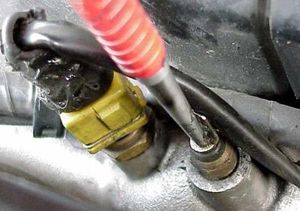
The coolant temp sensors are a pair of electrical sensors mounted to the upper coolant pipe on the front of the engine.
They are sometimes distinguished by calling one the "coolant sensor" and one the "water sensor," but they measure the same thing--the temperature of the coolant flowing past them. The difference between the two is their application. One is for ECU, and one is for the gauge.

ECU Coolant Temp Sensor
The left sensor, with a yellow connector and two terminals, is used by the ECU to read the coolant temperature. It does this by way of a thermistor--a resistor which changes resistance based on its temperature. The resistance readings correspond to numerical temperatures, as described by the FSM in the following chart:
| Temperature |
Resistance |
|---|---|
| 68°F |
2.1- 2.9 kΩ |
| 122°F |
0.69 - 1.0 kΩ |
| 176°F |
0.3 - 0.33 kΩ |
It should be noted that while the relation between resistance and temperature is nearly linear, it is not actually so. The ECU uses a table to convert the sensor's delta voltage into a temperature, which is then used in calculating and controlling various engine control functions. For more information, see the ECU article.
When this sensor fails, it usually does so without throwing a code. Rather, it simply reports the wrong temperature to the ECU. The symptoms of a failing coolant temperature sensor include:
- Hard starts when cold.
- Hard starts when hot.
- Rough running when warm.
- Auxiliary Fan runs constantly.
Gauge Coolant Temp Sensor
The right sensor, with a single-wire black connector, is used by the gauge cluster to indicate the coolant temperature on the coolant gauge. It uses a thermistor, like the ECU sensor, and is functionally the same as the ECU sensor (and the fuel temp sensor!). The only difference is its form factor, and the fact that it receives its ground connection through the pipe threads rather than a dedicated wire as on the ECU temp sensor.
It should be noted that while the gauge temp sensor does read and report a wide, varying range of temperatures, the gauge cluster practically only has three positions: cold, operating temp, and overheating. This is designed (on purpose) into the gauge.
Jumpy Gauge Needle
The electrical connector terminal on the gauge temp sensor is secured to the sensor with a rivet. Over the years, this rivet tends to works its way loose. This causes a bad connection, and the needle on the gauge will sporadically drop (especially under acceleration) or jump up and down.
This is an easy fix one can do with a punch. Pictures courtesy of Robo's Site, twinturbo.info.
- Remove the electrical connector from the gauge sensor.
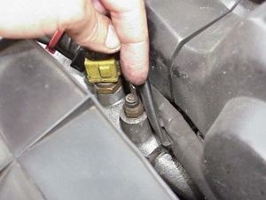
- Place the punch on top of the rivet and strike it with a hammer to flatten it, so the electrical connector becomes solid again.
- Clean the electrical connector to remove any debris or corrosion.
- Reconnect the electrical connector to the gauge sensor.

