Lifter
A Hydraulic Valve Lifter (often called Lifters or Tappets) is a device that is used to bridge the gap in between a camshaft's lobe and the top of the valve assembly. Older vehicles used shims which required periodic adjustment, whereas hydraulic valve lifters automagically fill with engine oil and expand in order to minimize such a gap as well as provide smoother, quieter engine operation without requiring difficult and expensive maintenance.

Contents
Location and Function
The Z32 features 24 valves, and requires a lifter for each one. Each lifter is mounted above its respective valve and below the camshaft lobe, essentially sandwiching it in between. As the camshaft rotates, there is a minute gap between the "circular" segment of the lobe's profile before the "tall" segment pushes against the lifter, which opens the valve. Using engine oil pressure, lifters expand to "hug" the cam lobe as much as possible. Aside from never requiring any sort of adjustment (which would be quite a task on the Z32), these lifters, when functioning properly, provide quieter engine operation.
[I would like a picture of a Z32 cylinder head with the cams out showing the lifters here, if anyone has one...!]
Failure
Lifter failure is quite common in Z32s. This is due to a combination of outside factors (such as low oil pressure due to a dented oil pan), age and use, and inherent problems with the lifter design. Most commonly, the tiny oil-feed holes on the lifters become clogged, allowing oil to eventually escape from the lifter without allowing new oil to enter. The lifter collapses (sometimes slightly, sometimes completely), resulting in reduced valve lift and a characteristic "tick tick tick" that follows the engine RPM by half (ie at 750 RPM, you would be able to hear 375 "ticks per minute"). In many cases, this can be solved by an oil change, and some have had good luck with various additives and cleaning fluids (like Seafoam, Heartland Xtreme Clean Engine Flush, Lucas Oil Additive, Marvel Mystery Oil, etc) to help clear up stubborn lifter tick.
In other cases, lifter tick can be caused by an outside factor, like low oil pressure (often from a dented oil pan, impeding flow through the oil pickup tube). In many cases, this causes multiple lifters to make noise. However, depending on the circumstances, this is often a symptom of a more serious problem, such as reduced oil pressure (which can severely damage the engine).
Rebuilding
As lifters are quite expensive to replace (about $33 ea, 24 required), it's common to rebuild them yourself. This can (and should) be done any time you are doing major head work on the engine.
Original writeup by Ash on TT.net

Tools Needed
- Something with considerable mass and a flat surface to strike the lifter against to remove the lifter body. A bench-vise with a flat anvil works wonderfully. It MUST have a flat surface or you will damage the lfiter during disassembly.
- A pair of pliers
- A small pick
- Red Scotchbrite pad
- 1500-grit finishing paper
- 1-gallon Carburetor Cleaner dip with parts bucket
- 1 quart of premium engine oil
- 1 can WD-40
Disassembly & Cleaning
- In order to remove the lifter body from the lifter housing, you must strike the base of the lifter housing in order to 'pop' the lifter body retaining clip free. This step takes a decent impact to accomplish - try progressively striking the lifter harder until the body pops loose, inspecting it after each strike until you get the feel for the right amount of force.
You will be able to tell if the lifterbody clip has released by looking across the base of the lifter from edge to edge. The lifter body will be at the same level as the base edges of the lifter housing. - With a pair of pliers, grab ahold of the lifter body and pull it out of the housing. Note the small dime-sized cap on the red cloth. This is within the assembly and you will need to get it out if it doesn't come out with the lifter body. Its just sitting in place so it will only need a good jostle to get it out.
- Open the lifter body by pulling the telescoping pieces apart. Be careful not to lose the compression spring inside.
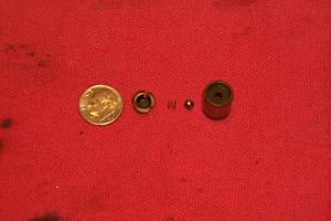 The checkvalve assembly is part of the smaller telescoping lifter body. I have disassembled this part to show the pieces and scale. They are very small parts. You can see how the checkvalve works - a small ball with a sealing seat and a spring to apply tension to the ball's position against the seat. This valve will let oil enter the lifter body, but it wont let it back out under normal conditions. When I have reconditioned my lifters, I left this part of the assembly together for fear of losing the small parts associated with it. The cleaning solution will remove any and all varnish from the parts and during the reassembly process there will be a step to ensure that the checkvalve is sealing. I would recommend not taking this apart and relying on the assembly check to determine if the valve is sealing, and if it doesn't seal up you can disassemble only the ones that would need further cleaning. These parts are just really small and easy to lose or damage. (Click for full size).
 - I use Gunk Carburetor & Parts Cleaner for all of my smaller engine parts that need to be cleaned. It comes with a parts basket that is perforated on the bottom to allow the cleaning solution to drain out when you remove the basket. This solution works incredibly well for engine parts. For your own protection, be sure to read the hazardous materials warnings on the container - this is not something you want to get on you. You can pick this up from any auto parts store for about $8 a can.
- Put your parts in the basket. Note I left the checkvalve assembly together for the dipping. I only show 1 lifter in the basket, but I was able to clean all of my lifters in 1 single dip. Just put the larger lifter housings in the bottom of the bucket first and all the smaller parts in the basket will fit on top and you can still close the lid. Let sit for about 2 hours for a thorough cleaning. You dont have to agitate this solution.
- Rinse all of your parts off with cold water. It helps to have an air compressor to blow the remaining water out of the parts. Once all the water is out, give them a good spray-down with some WD40 to displace the water and keep them from oxidizing.
- Using a red Scotchbrite pad, be sure to give a good once-over on the surfaces of the lifter housing that contact the camshaft and the lifter bucket, as well as inside the housing where the lifter body inserts. The lifter body's telescoping surfaces should also be deburred. This is preparing the parts for re-mating since you wont be getting every single lifter together with the exact components that were originally in it. This wont cause any problems but it is advised not to do this excessively.
During this step, pay special attention to the crown of the lifter. This is the area that the camshaft contacts and it has a small hole in the top-center. If you see any abnormal pitting on this surface, particularly around the hole in the center of the crown, the lifter will have to be replaced. It is normal for there to be some light surface patterns that are worn in due to the camshaft lobe, but these markings should completely disappear when you hit it with the scotchbrite. If you find yourself rubbing and rubbing on a particular spot to remove a blemish, it is likely a low spot or the metal has galled. If this is the case, you gotta replace it or this will cause damage to the camshaft.


Reassembly
- You will first need to install the spring into the larger lifter body.
- Fill the lower lifter body with oil. Leave about 2-3mm shy of completely filling the body.
- Then install the smaller checkvalve assembly with the checkvalve going first into the lower body. When you squeeze this together, you are going to have some air in the assembly. Using the pick, gently press onto the checkvalve ball while squeezing the body together. The air in the body will flow out as well as some of the oil - be sure to bottom the checkvalve body into the lower body and while holding, remove the pick. Slowly allow the two bodies to extend while the internal spring pushes them apart and take note of any air bubbles that might get sucked back into the body - they will be floating in the oil you can see through teh bottom of the checkvalve assembly. Once it has extended to full length, try compressing it again. It shoudl not compress at all. If you have oil come spouting out of the valve, try compressing and releasing it a few times as the ball may have become uncentered over the seat. If it still does not seal up disassemble the entire component and clean/inspect. If all is well, you are ready for the final assembly.
- Place the cap onto the checkvalve body. This is what the body will look like once it is assembled.
- Now the installation of the lifter body is kind of tricky. You have to be careful with the cap as there is nothing holding it in place here except gravity. It is important when the lifter is reassembled that this cap is in place just as you see here in the picture. You will need to hold the pieces as shown in the picture and carefully slide the body into the housing.
- Once you have the body in the housing, it will require a good squeeze to get past the retaining clip of the lower body. You must also ensure that you have the lifter body aligned into the housing's bore or you'll squeeze all day long without any success.
- To restore the finish on the housing I used a piece of 1500 grit paper. This will provide a really smooth surface free of burrs.


Be sure to inspect the camshafts for signs of uneven wear, dings, or burrs. I typically use the red scotchbrite on the journals and lobes to clean up the surface and prepare it for assembly. The lifter buckets (in the cylinder head) are also prone to getting dinged up during the valve spring installation - be sure to inspect them for any defects prior to installing the lifters. The lifters should drop right into the buckets with no force required.