Clock Spring
The clock spring (also known as a slip ring, or spiral cable) is a device that carries electrical signals to and from devices mounted to the steering wheel. It also serves as a steering angle sensor.
Contents
Function
The clock spring provides a few basic functions:
- Carries signal from steering wheel cruise control buttons (non-airbag models).
- Carries signal from horn pad.
- Carries signal to/from air bag model (on equipped models).
- Provide steering turning angle to the ECU.
Clock Spring
The necessity for the clock spring, however, is to accomplish all of these tasks while allowing the steering wheel to rotate.
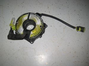
Non-airbag clock springs accomplish this by utilizing circular metal rings on one side, with metal spring brushes on the other side. Like a toy slot car, the steering wheel rotates the brushes, which ride along the rings, maintaining a constant connection regardless of rotational position. Airbag clock springs instead use an actual spiral cable, wound several times to provide flexibility while turning the wheel. The steering angle sensor is mounted to airbag clock-springs by four philips screws.
Steering Angle Sensor
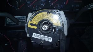
On twin-turbo models, the clock spring also houses a steering angle sensor for the power steering system. It utilizes a disc with nearly 360 1-degree slits (and one larger "straight-ahead" slot). This functions in similar way to the Crank Angle Sensor: a light is shined through the slits and a photocell on the opposite side detects light flashing on and off as it passes through.
Versions
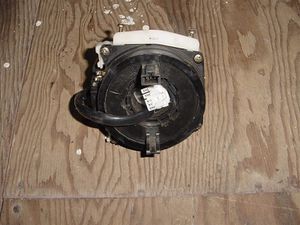
There are four versions of the clock spring for the Z32.
| |
Without SRS |
With SRS |
| Non-Turbo |
SEVERE LACK OF IMAEG D: |
|
| Twin Turbo |
Failure & Repair
The optical ring (steering sensor) of the clock spring is quite robust and practically never fails. The clock spring, however, does tend to fail.
Without SRS
On the non-SRS clock spring, the tracks and brushes become dirty, and the connection is degraded until none is made at all. When this happens, the optical ring should either be repaired or replaced outright.
The non-airbag clock spring can be disassembled quite easily. It's only held together by a few philips-head screws and plastic tabs. Once disassembled, the brushes and tracks simply need to be cleaned to restore functionality. Isopropyl alcohol and cotton swabs work great.
With SRS
The SRS spiral cable is a bit more tricky to take apart.
Thanks to Toasty at ProjectZ32 for the writeup and pictures!
Tools Needed
- Tamper-resistant Torx 50 bit.
- Philips & flat head screwdrivers.
- 19(?)mm socket
- Steering wheel puller
Procedure
- The easiest way to see if your horn works but the buttons aren't working is to roll down your window, lock your door with your key, and reach in and unlock it from the inside. This will set off the factory alarm which uses the horn. If it makes noise then your horn still works. If it doesn't your problem may lie somewhere else or your factory alarm may be disabled.
- You will need a "tamper resistant" Torx 50 male bit. Its a 6 point star with a circle cut out in the center. We located ours in a many piece set at harbor freight for $15. If you cant locate one you could also get a regular Torx 50 and drill out a hole in the middle. You will also need a steering wheel puller.
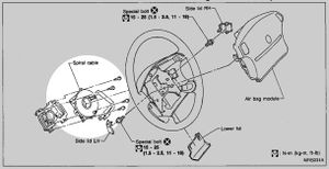
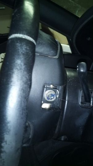
- Locate and remove the two "special" bolts that require the Torx 50 and remove them. They are at the 3 and 9 o'clock positions of the wheel.
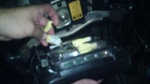
- Undo the two clips that are at the six o'clock position of the steering wheel. Your airbag package should come off easily. Set it aside and resist the urge to hide it in your couch cushions and mess with your friends.
- Lock your steering wheel so that you may remove the large hex nut in the center. Once that's off use the steering wheel puller to crack that baby off.
- Using a Phillips head screwdriver you will need to undo the screws holding on the plastic piece on the bottom side of the steering wheel neck ma bob and the bottom part of the dash underneath the steering wheel.
- Unscrew the four screws holding the assembly on and it should come out, use a smaller screwdriver to remove the screws attaching wheel position sensor to the assembly, and unclip any remaining connectors.
- At this point you should be able to pop in your new assembly in and button it back up. If you swapped your wheel position sensor disc over to the new assembly make sure the rectangular cut out is on the same side as where the sensor clips up. it will be a little bit off center and that's normal. If you are curious and want to open it up, keep reading. The assembly does say do not disassemble or tamper, but its a sticker, not your mother.
- There is another Tamper Torx bolt in a very small size on the clear plastic area of the side. Not sure if this needs to be removed but we did.
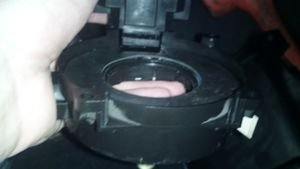
- The side with the position sensor disc has three small plastic clips holding it in, use a Flathead to pop it off
- In the center of the other side are two larger clips press these in to pull the assembly into two halves. Be careful not to pull it apart with too much force as you may break the ribbon cable if it isn't already broken. The ribbon cable however is pretty long and it may be difficult to break it in that manner, but still be careful.
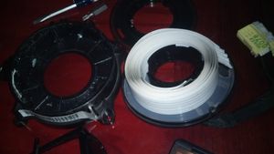
- You have it fully disassembled at this point!If your ribbon cable looks intact you could check for continuity using the pins on the connectors. If that all checks out your problem is somewhere else
