Boost Controller
A Boost Controller is a device that allows the user to adjust the boost pressure produced by the turbocharger(s).
Contents
Function and Necessity
The stock twin turbo Z32 has a basic boost-control system from the factory which basically allows to stages of boost pressure to be produced. Under normal operation, the system produces approximately 9.5 PSI of boost. When in safety mode, this is reduced to 7 PSI.
As owners upgrade their vehicles, increasing boost pressure is a quick and effective way to drastically increase power. However, with no means of control over boost pressure, the turbochargers will continue to produce boost pressure as high as they can. This can be extremely dangerous and will practically always end in catastrophic engine failure. A boost controller allows the user to both increase and limit the boost pressure. Typically, ~12psi is a safe spot for a stock Twin Turbo with a stock ECU. An aftermarket ECU can usually take it up to 14 PSI, and 16 PSI should not be exceeded on 91 octane. Of course, the modifications and condition of each specific car will affect this, as well as the owner's personal preference (between safety vs power).
For more detail on how boost controllers work, see the "Electronic Boost Controller Supplement."
Types of Boost Controllers
There are essentially two types of boost controllers available:
Manual Boost Controllers

Manual Boost Controllers (MBC) are a mechanical device that works by restricting the amount of positive pressure to bleed through to the wastegate actuators. This is achieved by either an adjustable valve (which varies the size of the internal passageway through which air flows) or a ball-spring valve (which uses a spring-loaded ball bearing to open and close, and is adjusted by changing the pre-load on the spring). Generally, the ball-spring type is a much more accurate and stable way to control boost versus the standard bleeder-valve type, and both of these can be had for well under $100.
Electronic Boost Controller

An Electronic Boost Controller (EBC) is a bit more complex way to control boost pressure. It's usually made up of three identifiable components:
- A solenoid valve.
- A control panel/box (to go in-cab).
- A boost pressure sensor (MAP sensor) (often housed inside the control panel).
In short, the boost controller uses a simple computer to vary the opening/closing rate (duty cycle) of the solenoid control valve to achieve the desired boost pressure level. The MAP sensor is used so the computer can receive an accurate reading on the intake pressure of the manifold.
There are many types of electronic boost controllers out there. To learn a bit more about how they work, check out the Electronic Boost Controller Supplement page.
Installation
Related Article: Vacuum Diagrams.
Credit to TwinTurbo.net for the basisof this article.
Tools Required
- 10mm Socket & Ratchet
- Philips Screwdriver
- Scissors and/or snips.
- Soldering Iron (EBC)
Materials & Parts Needed
- Approximately 10 - 20 ft of 1/4" vacuum hose.
- Wire/coat hanger (EBC)
- Solder, electrical tape, heat shrink tubing, general soldering equipment. (EBC)
- Drill, self-tapping sheet metal screws depending on installation preference.
- Rubber vacuum caps
- 1/4" vacuum line couplers and T's.
Wiring Harness (EBC Only)
The first step is to splice into the ECU's wiring harness. This is necessary as the boost controller monitors various aspects of the engine to determine how to vary the control solenoid.
- Every boost controller is different, but there is generally a harness connecting the solenoid valve (and sometimes the MAP sensor) to the boost control unit. As the control unit will be mounted in the cabin with all the other components in the engine bay, it is first necessary to run this line through the firewall.
First, disconnect and remove the battery. - Remove the rubber shielding in the battery area to expose the opening into the fender well.
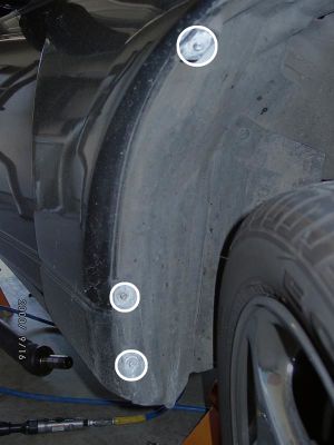
- Turn the steering wheel all the way to the right to gain access to the fender liner screws. Remove them (3 x Philips screws).
- It will take a bit of fussing, but pull out the rubber boot that goes through the firewall. If you carefully notch it with some snips, you can "plug" the rubber boot back in with your boost controller harness in place.
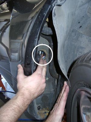
- Run the wiring harness for the boost controller through the hole by the battery, and pull some extra slack so it can pass through the firewall.
- Tape the wiring harness to a long wire (a coat hanger works great), spray it with some WD-40, and run it through the firewall port. The coat hanger allows you to easily guide the harness through to the other side. After it's through, of course remove the coat hanger.
- Note: If your boost controller has an integrated map sensor (instead of a standalone one), now is the perfect time to also run a vacuum line from the engine bay through the firewall to connect to the control unit.
- Replace the harness boot in the fender well.
- Replace the screws to the fender liner.
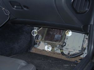
- Pull back the carpet by the passenger's feet to expose the wooden ECU cover.
- Remove the 4 x 10mm bolts holding the cover down. (White circles. It's not necessary to remove the other panels [yellow circles]).
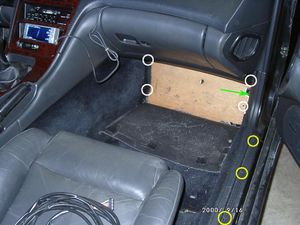
- Remove the wooden ECU cover, then remove the 3 x 10mm bolts holding the ECU bracket to the chassis.
- Remove the 10mm bolt securing the wiring harness to the ECU.
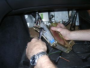
- Each boost controller will have its own set of necessary connections to make, and its manual should detail where each lead connects. You'll now have to splice the boost controller's harness wires into the ECU harness. This can be done by carefully removing some of the insulation from the appropriate wire and soldering the new wire to it, or using "vampire clips" included with many boost controllers today, allowing you to simply clip the new connections in.
The following table details the most commonly used pins by boost controllers. For more information, check out the ECU Harness Diagram.


| Function |
Wire Color |
Pin Number |
|---|---|---|
| Ignition Power |
White |
59 |
| RPM |
Yellow w/Red Stripe |
07 |
| Ground |
Black |
50 |
| Throttle |
White |
38 |
| Speed |
Yellow w/Green Stripe |
53 |
- When you're all done, connect the battery and boost controller (as per the controller's manual) and turn the key "ON" to make sure everything is hunky-dory.
- Connect the ECU harness connector while screwing in the 10mm bolt that secures it. Gradually alternate between tightening the bolt and pushing on the harness connector. Make sure it's fully seated before you continue.
- Turn the key ON again, just to make sure nothing is shorting out now with the ECU harness connected.
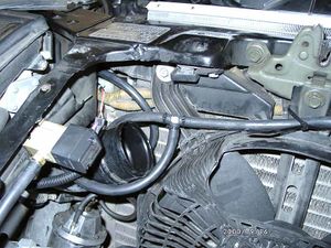
Vacuum Routing & Engine Bay
- For EBCs, mount the boost control solenoid in the engine bay in a place of your liking. This is usually where self-tapping sheet metal screws come in handy. Some popular places include:
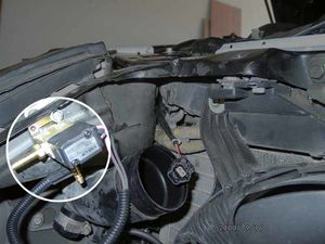
- Under the nose panel near the frame rail.
- Where the HICAS solenoids used to be.
- On the firewall near the battery.
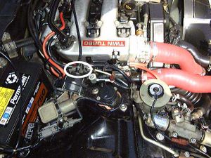
- Remove the driver's side large intake hose that runs from the front (by the radiator) to the throttle bodies. Plug the hoses so nothing can fall in.
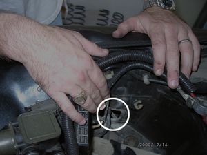
- Disconnect the vacuum line that connects to the nipple on the underside of the hard pipe which runs to the throttle bodies.
- Run a new vacuum line from this port to the NO port (normally open) port on the boost control solenoid.
- Remove the passenger side throttle body hose as well.
- Remove the vacuum hose form the underside of the throttle body as you did in step 3. This time, cap off the port on the hard pipe and secure the cap with a zip tie.
- Feeling towards the end of this line, you will find a "lump" a few inches in. Cut the line past this lump to remove it--this is the "stock boost jet" restrictor. Repeat for the opposite side.
- Connect a vacuum line coupler to the line you just removed from the hard pipe. Repeat for the opposite side.
- Join these two lines at a T-fitting (location and lengths will vary depending on your personal setup).
- Run a vacuum line from the 3rd port of the T fitting in step 8 to the COM port (common) on the boost control solenoid.
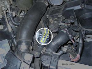
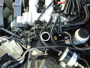
- Locate the line on the balance tube which runs to the factory boost pressure sensor by the driver's side fender.
- Cut this hose, install a T-fitting, and run the 3rd leg of the T to your boost pressure sensor.
- If your boost control unit has an integrated MAP sensor, this will be the line you ran through your firewall previously.
- Refer to the "Twin Turbo (Modified)" and "Twin Turbo (stock)" diagrams on the Vacuum Diagrams page for further clarification of the vacuum system's layout.
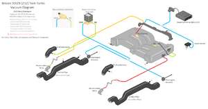
- Note: The above process utilizes the factory lines to connect to the wastegate solenoids. Some owners, especially those who have removed AIV/EGR solenoids, will prefer to remove ALL the stock boost control lines and run brand new lines all the way to the wastegate solenoids. In this case, your system will more closely resemble the "Twin Turbo (Modified)" diagram (shown above).
- On each side of the engine is a black connector with a red clip on the end. These control the factory wastegate solenoids--disconnect them both.
- Replace the throttle body intake hoses. Don't forget to remove the towels you stuffed in there!
- Start the car and check for vacuum leaks.
- Configure your boost controller as per the manual's instructions.


