Cylinder Head
A cylinder head is one of the major components that makes up an internal combustion engine. Bolted to the top of the block, cylinder heads house the valvetrain for each cylinder in one unit, and usually have an "intake side" that attaches to the intake manifold, and an exhaust side that attaches to an exhaust manifold. From a mechanical standpoint, cylinder heads make up the "ceilings" of the combustion chambers. They often serve some additional functions (such as being mounting points for accessories), as well.
Versions
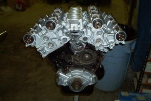
The Z32's (or, more specifically, the VG30DE/TT's) cylinder heads are made from cast aluminum. They feature 24 valves (4 valves per cylinder) with self-adjusting hydraulic valve lifters. The turbo models featured inconnel exhaust valves to withstand hotter exhaust gasses.
There were a few different versions of cylinder heads put in the Z32.
| |
Non-Turbo |
Twin Turbo |
| Phase I |
90-92 (30P) |
90-94 (40P) |
| Phase II |
93-96 (10Y) |
95-96 (48P) |
Generally speaking, the TT heads flow better than NA heads and can be considered an upgrade if installed on an NA, albeit a minor one. The 48P (late-style) TT heads also had a slightly casting change compared to 40Ps. Some have claimed that they flow better, but this has not been confirmed, and the car was rated for the same horsepower. There is also a difference in "old style" (P1) and "new style" (P2) heads. As the P1 and P2 shift marked a change in fuel injector design, the fuel rail had to change. This meant the lower intake manifolds had to change, and the ports on the intake side of the heads changed as well. For this reason, new style intakes are incompatible with old-style heads, and vice-versa. The proper way to install P2 injectors on a P1 motor is to either have the lower intake manifold machined to accept the P2 fuel rail, use an aftermarket fuel rail, or simply use a Deatschwerks-style adapter kit.
Problems
As with any complex mechanical part, Z32 heads were not without a few faults.
Soft Valves
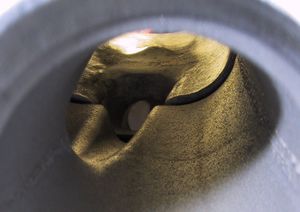
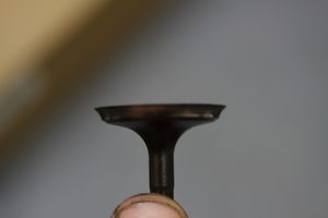
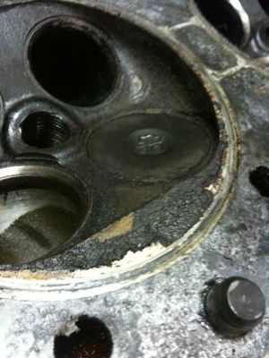
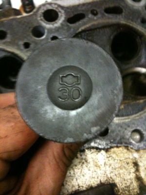
Very early 1990 heads had an issue with the intake valves being made from inferior metals, eventually causing the valve to wear away where it meets the head and cause a loss of compression. These valves were stamped "30". Later intake valves, which corrected this issue, were stamped "EG".
Images courtesy of aliaZ from twinturbo.net.
| Click images for full-size views. | ||
CAS Pin Alignment
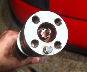
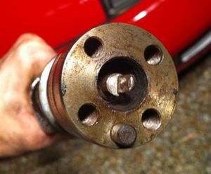
Very early 1990 heads were machined improperly and caused the crank angle sensor to become misaligned with the cam shaft. This would slowly cause the teeth on the CAS alignment pin (either on the CAS itself or the cam, or both) to wear down and make the reading wander. The loss of alignment teeth can also cause detonation, random missing, and various other running issues. Jim Wolf Tuning released an article detailing their solution for the problem, as well as an announcement for a chromoly CAS alignment pin, which they still sell.
| A good CAS drive pin (left) compared to a heavily worn drive pin (right). Click images for full size views. | |
While both of the above problems are serious, most cars on the road today either never suffered from them to begin with, or the problems have long since been dealt with due to the severity of the issues they cause.
Lifter Tick
Main Article: Lifter.
The Z32 uses a total of 24 valves (12 per head, 4 per cylinder). Each valve has its own hydraulic lifter, which is used to fill the gap between the camshafts' lobe and the valves, reducing engine noise. However, the lifters themselves feature multiple moving parts and rely on easy oil passage through tiny ports. Over the years, their checkvalves become tarnished and the oil feed holes become clogged. This results in lifters that either can't fill with oil or don't properly retain the oil they should. The lifter collapses (if only slightly), causing the cam lobe to strike the top of the lifter every rotation. This produces a characteristic "tick-tick-tick" noise heard from the upper part of the engine. The ticking is easily identified as lifter tick, as the "ticks per minute" is exactly half of the engine's RPM, and the noise comes from the top of the engine (rather than the lower rotating assembly).
