A few months ago, I posted showing how I eliminated the stock fuel pump control unit in favor of a fixed-voltage setup and a bigger FPR to handle the additional fuel flow. When I did this mod in November, this was mostly accomplished by effectively grounding out the ground wire leading to the pump, since the FPCU otherwise modulates the ground side to control the fuel pump speed.
However, after driving around for a few months, I noticed the car wasn’t holding fuel pressure at higher boost levels (say, 20 PSI). At first I compensated for this a bit in the tune, but quickly realized something was wrong. To troubleshoot, I replaced the primary fuel filter, the pick-up sock on the pump, and even the fuel pump itself (a Walbro 485). Upon replacing the pump, it seemed to be solved at first. My AFRs were back where I expected them, probably due to the compensation in the map I had done, but the fuel pressure still didn’t seem to be following the boost up as it should. Sure enough, after another month or so, I could watch the fuel pressure peak at 4.3 bar, then taper down as low as 3.9 bar. It should have been peaking at 4.4 bar and holding it or very nearly (most boost controllers allow the boost to taper off slightly, which is normal).
Having exhausted pretty much all of the obvious options, I began to wonder if the stock wiring was the cause. Naturally, the first step was to start looking around online to see if other users experienced similar problems with the 485. It’s most commonly used by GT-R and Evo guys, and neither of them seemed to have any issues with it. In fact, it was pretty well established in the GT-R community that it could power 1000awhp+ on E85, so I didn’t think I was maxing out my pump at a meager ~480whp.
But on TT.net, I started finding a few clues, in posts like these:
I had two Walbro pumps with stock wiring. I saw the fuel pressure couldn’t rise with the boost pressure. I changed out to thicker gauge wires, the problem was solved.
I’m not saying the stock wiring will burn out with two pumps, but it can’t supply enough amperage.
I work with low voltage wiring for my job every day. Here is the main issue with this set up.
The harness coming from the body harness running to the fuel pump itself is 18awg wire. 18 gauge wire is rated at 10amps. Here is a chart showing the draw of 1 walbro 255 pump
Oh, and that last one was accompanied with a few pictures, like this.
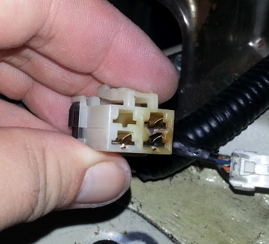
Burnt Fuel Pump Connector, from running dual pumps on stock wiring!
Granted, these users were talking about dual Walbro 255 setups, but a quick look at Walbros specs for the 485 indicate that this could indeed be a limiting factor even with a single pump.
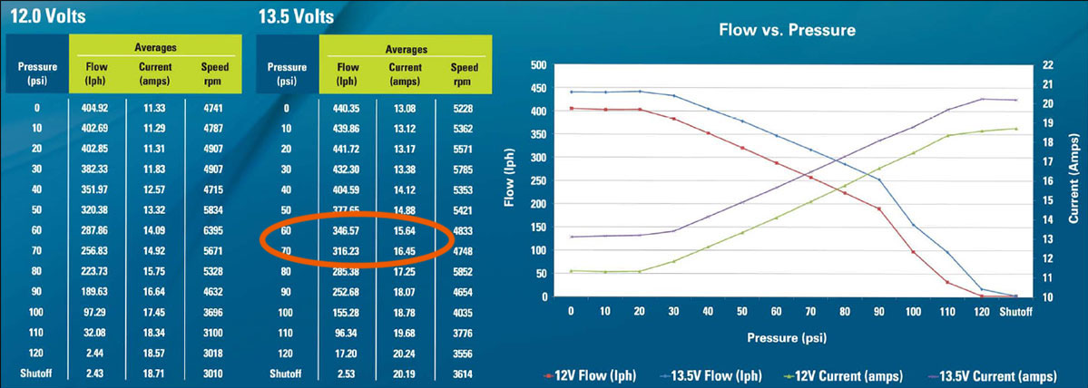
I circled the range of pressure I was attempting to hit.
Clearly, this put us outside the operating range for the stock 18awg wiring. When I examined the bulkhead, the (orange) power supply wire going up to the bulkhead was very clearly a heavier gauge, closer to 14 or 12awg. But the ground wires on the bulkhead were much smaller, at about 18awg, and the power supply wire going into the bulkhead itself (becomes white w/ black stripe) is clearly a tiny 18awg. Why Nissan decided to reduce the gauge so much at the very last step in the fuel pump circuit is beyond me, but they did. I checked out an extra Walbro pigtail I had, and it was 14awg, which is good for up to ~24 amps, which gives it a bit of a window of safety, too.
Now, at this point, I could have run a new wire from the battery to a new ignition-operated relay, but I really wanted to keep the stock relay and wiring in place. This allows the fuel pump to be activated by the ECU, so it only runs when the engine is turning, plus the short prime before and after running. The wiring at the FPCU connector on the chassis appeared to be that same 12-14awg, and it had a convenient ground point right next to it. When you look at the wiring diagram, you can see that the harness basically gets power from the relay (not pictured), then Ts off and runs to the FPCU and to the pump. Again, the FPCU modulates the ground to change the speed, so in my setup I simply needed to get it power and ground.
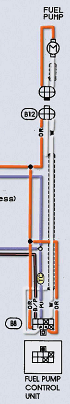
For some reason, the power wire also Ts off on its way to the FPCU, but just looking at the diagram appeared to indicate that using the outside-most pin (top-right if you’re holding the harness connector in your hand and staring at the female pins on it) made the most direct connection.
At this point, I decided to run a new harness directly from the FPCU connector on the chassis harness to the bulkhead, giving the fuel pump a direct, solid connection of 14awg wiring without worrying about where the OEM harness may or may not reduce down to 18awg. First, I started by making a custom harness. This was done by using the male connector I previously removed from a bad FPCU sitting around, and it only has one wire going to that orange wire pin. It runs alongside a ground wire, which uses a 12-14awg eyelet crimped and soldered on the end.
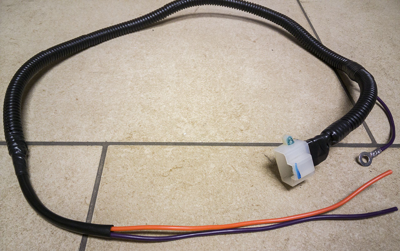
Custom fuel pump power supply harness.
Orange is power, and purple is my ground. The pigtail at the end will be routed onto the fuel pump bulkhead to connect to the pump. To do this, I literally just drilled a hole in the boot on top of the bulkhead (be sure not to catch any existing wires!)
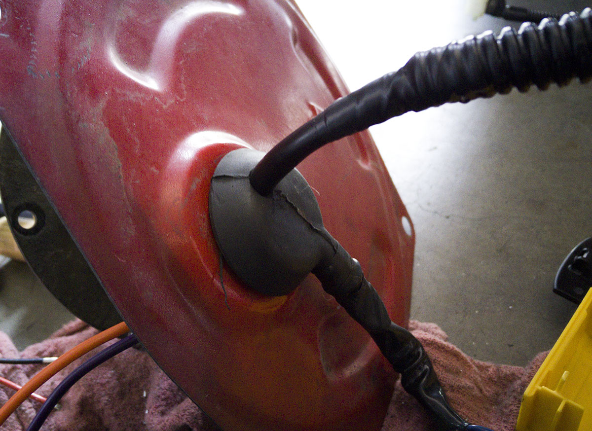
Easy Peasy.
Now at the bulkhead itself, there are several plastic pass-through connectors which are sealed, to get wiring inside the tank without any leaks or anything. They don’t appear to be removable, and I don’t know how heavy duty they are anyway, so I just desoldered the two that actually go straight to the pump, as I didn’t want random hot wires hanging out in the tank. Then I drilled a few holes…
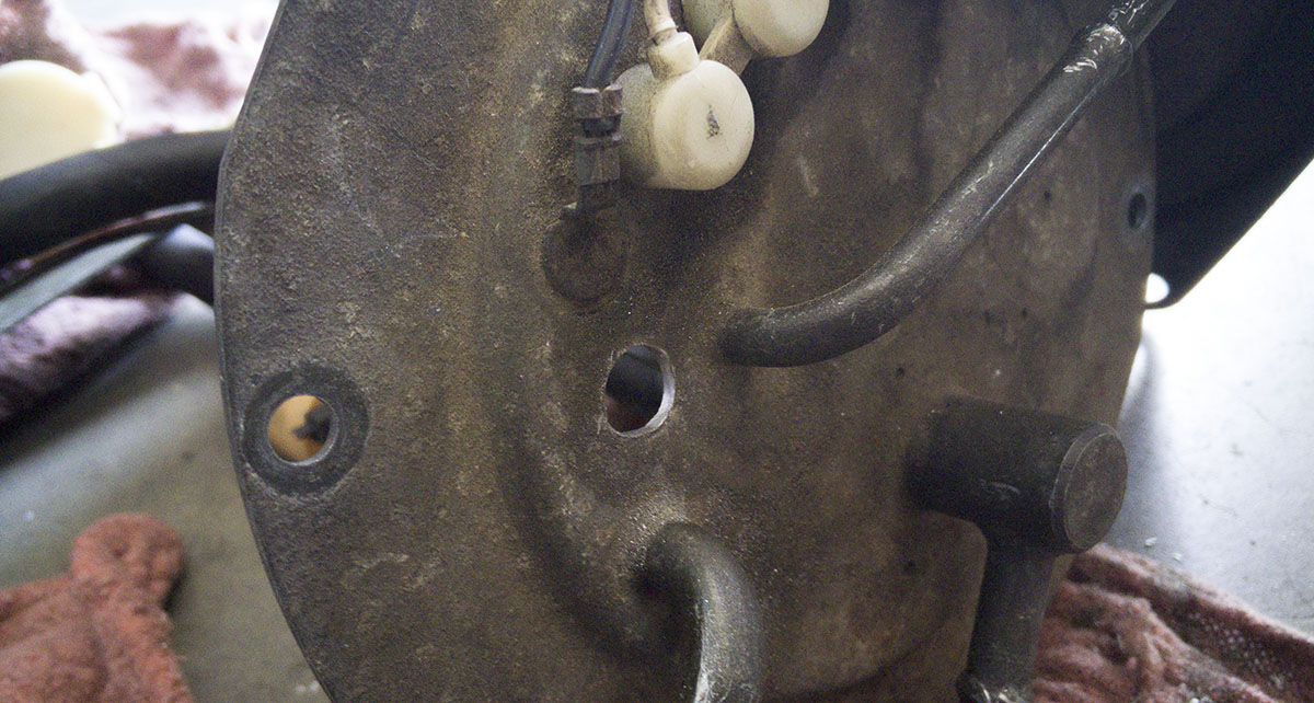
Gulp.
These would receive rubber expanding well nuts, which look like this.
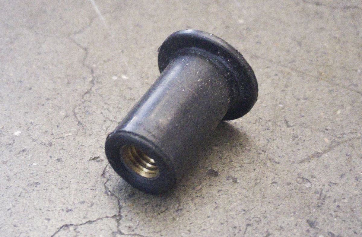
Rubber Expansion Well Nut
These have a threaded portion in the bottom. You put them through the hole, and when you tighten a bolt into the threaded portion, the rubber bit collapses and creates a donut. So it creates a seal, and provides a method to get electricity safely through the bulkhead!

The underside of the bulkhead, with the well nut installed and a bolt threaded through. You can also see the stock point from which I removed one of the original wires.
On the underside, a washer and nut secure the eyelet running from the fuel pump itself to the well nut. Sorry, no pictures of this, but it’s pretty self-explanatory. I repeated the process and installed a second well nut, one for power and one for ground. You can see how they were installed here (it’s basically the same underneath).
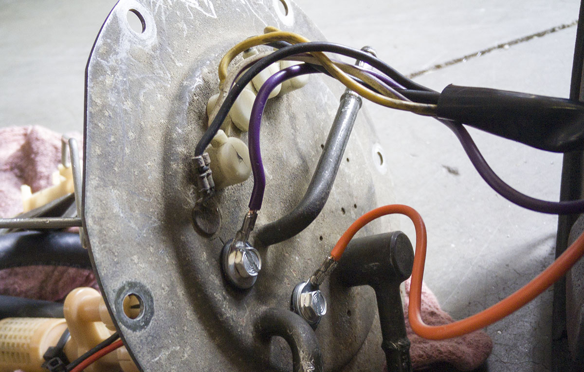
Orange: Power, Purple: Ground.
Again, connectors are crimped and soldered just to be sure they don’t wriggle loose or anything. It is true I could have grounded the pump directly to the bulkhead, you can see I even put the new ground adjacent to an old stock one, but I wanted to supply a clean, solid ground directly to the pump without worrying about how electricity was going to make its way back across the tank, tank hangers, chassis, etc.
And that was basically that. The harness runs from the top of the bulkhead directly down to the FPCU connector. There is a stud in the chassis onto which the stock FPCU bolts; I used some sandpaper to brush off the paint and make sure it was getting a solid connection. The old 3-wire rectangular bulkhead connector is just left disconnected. To my delight the fuel pump primed and didn’t burst into flames when I turned the key, and as you’ve probably guessed by the fact that I’m even writing this article, this did the trick. After several test runs, it holds solid fuel pressure at 4.4 bar through the entire run. I even had to pull a ton of fuel around the top-end of my fuel map to keep the car from running pig rich. Time will tell how the well nuts hold up, this is the first time I’ve used them, but they appear to be working well so far.
I don’t plan on making ridiculous amounts of power on this car any time soon, 500+ is where I’m aiming. But in the future, you could very well switch to a dual fuel pump setup without changing a ton here. My idea would be to run a second well nut to supply power to the second pump. I would use a boost-pressure activated switch to kick the second fuel pump on at, say, 10 PSI. The boost switch would activate a relay (Bosch 30A) which would supply power to the second pump. The two pumps would T-their output together, but at that point you may want to start thinking about heavy modification to your bulkhead and running -8 AN fittings or something along those lines.
That’s all for today. Until something else breaks!
think this is happening with my track Z?
I definitely think it’s worth looking into. My ears kind of perked up when you and the other two guys running 485s mentioned you were having lean issues at the Pavillions the other week.
Another great writeup Nick! Very helpful
A note from my own experience following this procedure: Make sure you do not over-tighten the well nuts! Too much pressure will cause them to split, at which point the terminal may make contact with the bulkhead. In my case, it was the power side, which burned up the insulation and wire on top of the bulkhead. Thankfully it did not ignite the fumes (which were present as the hole was slightly open) and burn the car down. It did, however, blow the green 30A FP fuse near the stock battery location under the hood. I have since replaced the well nuts (which now the ground side is splitting due to a burr from drilling) and added a 25A bus fuse in line with the power wire feeding the pump. My plan is to hog the holes out about 1mm more, then file away all burrs so it is a nice, clean, smooth surface. I used Hillman 1/2″ well nuts from Lowe’s, around $0.90 each.
That’s not good! Glad you caught it in time, though. I’ll have to double check mine as it’s been a few months, but when I was playing with them I did find they’re a bit easy to split if you’re not careful.
I know this was nearly 7 years ago but Dude this same thing happened to me I overtightened the well nuts and I was wondering why the 30a fuse kept blowing to find them torn to shreds and pump positive terminal snug against the sending unit. Should have read through this comment section first rookie mistake. Hope you doing well
Hey Jack, after 7 years, mine gave up too, but a different method! The rubber had shrunk just enough that the washers were no longer tight enough to make good electrical contact. I ended up replacing it with a nice set of Radium harnesses!
Interesting. Looking around about this subject shows similar problems, well I mean problems related to the fuel system. You could have hooked the new connection straight to the battery with a relay, take the power output from the factory fuel relay to use as the control signal with your new dedicated cable. I always upgrade the wire to the fuel pumps if they are upgraded. I allow for the wire capacity (A) to have an extra 1/4 to 1/3 of the required max draw (A), increasing the AWG as required. Be careful to check the drop in current based on the wire length, the pumps a good distance, and that the wire you use isn’t copper coated aluminum (which is light weight) it carries about 30% less current than the same AWG size. Heat also has a big effect, and heat and peak current over a period of time.
The factory setup, the FPCU is probably switching the pump control to control it, this would use less power than a directly wired system. Once the wires get cooked like that they shoule be replaced. Putting a nee fuel pump in would eventually kill that pump. The better a pumps power supply is the longer it will last.
I like to use 10 or 12 AWG minimum, and never have power problems.
are you running this harness with a fpcu or without??
Nope, no FPCU. That’s the point, deletes the FPCU completely!
anymore pictures of the wiring where does it feed from the fpcu plug?
Great read!!!
Why would you want the pump to run full speed all the time? There’s benefits in what the factory did by slowing down the pump when it’s not in WOT demand. Specifically, lower fuel temps, less evaporative emissions, and a more consistent air/fuel ratio. If there was a voltage drop due to an undersized ground (18g is ridiculous), then some voltage drop tests would conclude which section of wire wasn’t getting it done.
It’s not about wanting to run the pump at full speed all the time, it’s done out of necessity. The factory FPCU simply cannot handle a higher-amperage pump like a Walbro 485, it just burns up after some time. Additionally, the Walbro is completely happy to run at 12v all day. By switching to a larger FPR that can return the additional amount of fuel, it negates any negative effects related to AFR or emissions. Plus, the turbine-style 485 is much quieter than the stock gerotor pump, so even at 12v you can’t hear it unless you put your ear directly against the chassis. And voltage drop tests aren’t really necessary, since we already know which section of wiring is undersized (passing through and inside the bulkhead).
Do you have instructions on how to delete the fpcu?
What kind of power did you make on this setup ?
I am going to be running a very similar setup, were you limited by the nismo 740s on e85 ?
how close were to maxing them out ?
On the butt dyno probably 450whp or so, but this was on very blown Sport 500s at about 20psi. The 740s can support close to 25psi, especially if you raise the fuel pressure, but I took the car off the road (currently under construction!) before getting that far. Talking to other people, the 740s are good for about 525whp on E85.
Is an aftermarket FPR required with this wiring change? Out of curiosity, what would happen if I didnt change the stock FPR?
I’m also using a walbro 485, any chance you are going to produce this harness in the future?
I personally would consider it a requirement with the 485. I’ve heard so many guys complain of fuel pressure issues with the 485, and they’re all still running even the stock FPCU. With a stock FPR, I would bet that you’re going to run way too rich at idle, and you could probably tune it out, but that’s kind of a sloppy way to do it. Unfortunately we don’t have plans to make a harness like this any time soon, demand is pretty low and the FPCU connector is a totally custom connector as far as I know, so the pricing wouldn’t really make sense. That said, Radium started selling a really great pass-through harness that makes this job a LOT easier and safer:
https://conceptzperformance.com/radium-engineering-fuel-pump-bulkhead-pass-through-harness-assembly-17-00xx_p_26591.php
Since the harnesses from radium engineering you suggested seem to be the same price, would you suggest getting the three walbro pump harness setup even though I only have one walbro 485 currently. I am just wondering if that might be the better way to go since I would like to go with a dual pump setup in the future. A triple pump setup is overkill but they don’t seem to offer a dual 485 harness. All they have is a single or triple
I don’t see why not! I’m not a huge fan of dangling connectors, and I can’t see anyone need triple 485s in these cars, but it wouldn’t really hurt anything.
Has anyone tried using AshSPEC
Dual Fuel pump control module?
You can replace the MOSFETs and anti-rolling diode in the FPCU for more amperage. 20A diode + 40A MOSFETs and it will sustain the walbro 450.
Using 2 FPCUs is just a killer.
Part numbers:
2x MOSFET STP40NF10L with insulation to the FPCU case
1x Diode F20UP60DN
you may also replace the original “7805” like 5V regulator with full automotive one and higher specs: L7805ABP
Have you tested this?
Yes, I’ve run this system since the post was made
I spoke with Ash at Ashspec and their modified controller can handle up 120amps 2x60amps. The 485’s use a little over 20 amps each.
Well,
Fitting a Walbro 485 in 300zx is a long-term adventure and require engineering skills.
I upgraded the FPCU:
_Thicker copper tracks on PCB
_MOSFET 2SK3715 (better than 2SK3705 on pictures)
_freewheeling diode F20UP60DN
_All the external wiring upgraded to 12AWG silicone wire to handle the ~20A of the pump.
Pictures are there:
https://photos.app.goo.gl/NSsyhKiWDNfVPkhB9
And I fitted the pump to the original lid:
_ribbed hose
_prefer nylon washers/sleeves to go through the lid (rubber will be eaten with E85)
_I replaced the fuel level sensor with a new unit from Nissan D22 pickup, the problem you need to adapt the float, but resistance range is the same (5 Ohms when full, 80 Ohms when empty)
_stainless screws everywhere
Results:
_low mode: pump gets 6V, 3 bars with OEM FPR and vacuum line disconnected
_middle mode: pump should get 7V, not tested but pretty sure I can get 3 bars too
_full mode: pump gets 12V, 4.1 bars !!! nothing less. OEM FPR cannot handle the flowrate
== > Fuel map needs to be fully revisited according to the pressures being jeopardized now.
I still have a problem with the FPCU: at low mode, the ripple current from the pump and MOSFETs is so high, the capacitor 47uF/63V (orange one after the coil) gets VERY HOT.
Even if it’s rated @125°C, this is a weakness now. Waiting for Rubycon 220uF/80V 130°C to replace it.
Does anyone have a write up on doing this with a duel fuel pump,relay and hoobs switch in a 2+2?
This is the kit that I use on any upgraded pump. I have one customers Z32 I installed 2 of these kits to support dual 485’s. Each pump was individually activated via ProEFI standalone system.
https://www.summitracing.com/parts/aei-16307?seid=srese1&gclid=Cj0KCQiAoY-PBhCNARIsABcz772KZMOlNztpC1l-GgQ-s7HJJEOJjb4O70w1QN_wFNUWF_KsfNW_zEsaAkpjEALw_wcB