Difference between revisions of "Vacuum Diagrams"
(Imported from text file) |
|||
| (4 intermediate revisions by the same user not shown) | |||
| Line 1: | Line 1: | ||
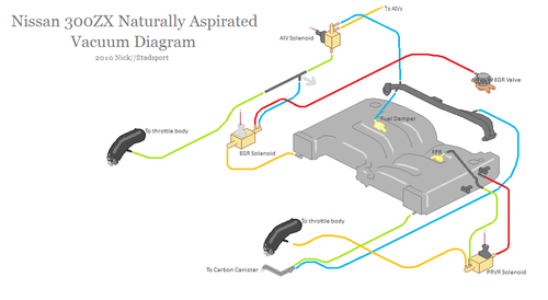
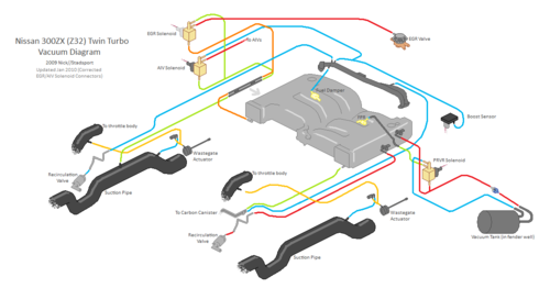
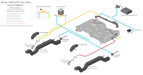
| − | These diagrams illustrate the vacuum system in the Z32.<br /> <br /> | + | These diagrams illustrate the vacuum system in the Z32.<br/> <br/> Note to editors: Please do NOT upload diagrams in a lossy format (such as JPG) as they severely degrade the image quality. |
| − | ===Naturally Aspirated Model (Stock)=== | + | === Naturally Aspirated Model (Stock) === |
| − | |||
| − | |||
| − | |||
| − | |||
| − | |||
| − | |||
| − | |||
| + | [[File:Nadiagram.png|500px|(Click for full-size)]] | ||
| + | |||
| + | === Twin Turbo Model (Stock) === | ||
| + | |||
| + | [[File:Manifold.png|500px|(Click for full-size)]] | ||
| + | |||
| + | === Twin Turbo (Modified) === | ||
| + | |||
| + | [[File:TT Vac BoostController.png|500px|(Click for full-size)]] | ||
[[Category:Diagrams]] | [[Category:Diagrams]] | ||


