Coolant Line Bypass
There are several metal coolant lines and vacuum lines mounted to the underside of the plenum. These serve to carry coolant to the throttle bodies as well as the turbochargers (in turbo models).
The throttle body coolant lines are widely considered to be an exercise in over-engineering and most owners delete them with practically no ill-effects. Removal of these line not only helps to simplify the engine bay and make future plenum pulls easier, but also reduce the number of potential sources of leaks in the cooling system.
Related Article: Intake Manifold Removal.
Once again, huge thanks to NytWolf and all others who have created original content such as the images and information you see below. Without people like these, this wiki wouldn't be possible.
Contents
[hide]Parts Needed
- 4 feet of 8mm rubber coolant.
- 3 feet of 6mm vacuum line (silicone is recommended).
- 2 feet of 4mm vacuum line (silicone is recommended).
Tools Needed
- 10mm socket & ratchet.
- Philips and flat-head screwdrivers
- Angle grinder, dremel tool, drill are preferable if removing the coolant line ports.
Procedure
Under-Plenum
- Remove the Intake Manifold.
- Being careful not to damage the plenum, set it upside-down to gain access to the piping attached to the underside.
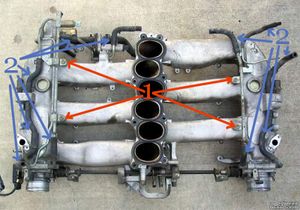
- Remove the 4 x 10mm bolts (Items 1) securing the hard lines to the plenum.
- Remove the millions of rubber lines (Items 2) connecting to these hard-lines and ports.
- Hang on to the springy hose clamps, we can re-use them in the next section!
- Be sure not to damage the air regulator pipes at the rear of the plenum.
- If you can't get these hoses off by traditional means, just cut them! You're removing them, anyways.
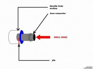
- Using a drill, remove the pins that secure these water line nipples into place.
- If you're having trouble removing them, you can cut them off with a grinding wheel (dremel tools work well). Be careful not to let any debris enter the plenum itself.
- You may have to remove the IACV and air regulator to remove the rear vacuum hard line. If you do this, be prepared to replace the fragile paper gasket that seals it to the plenum.
- After drilling, use some pliers and twist the ports out until they're out.
- Use your cutting tool to remove the rest of the metal hard lines until...
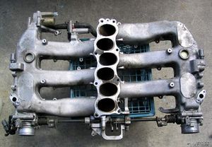
- Voila!
On Engine
Now that we've eliminated a million pipes and fittings under the plenum, we need to compensate for these changes by re-routing some cooling system lines in the engine bay.
NAs-- Skip ahead to the NA Diagram.
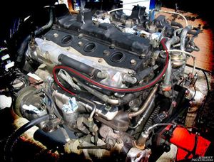
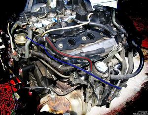
- Run approximately 2 ft of 8mm water hose from the upper port on the driver's side heater core pipe to the turbo coolant feed, as shown in red below. Be sure to use clamps on the ends of the hoses (if you salvaged the hose clamps from under the plenum, those should work great).
- Moving to the passenger side, run approximately 1 ft of 8mm water hose from the lower port on the driver's side heater core pipe to the turbo coolant feed, as shown in red below. Be sure to use hose clamps on the ends of the hoses (if you salvaged the hose clamps from under the plenum, those should work great).
- Run about 2 ft of 4mm vacuum line from the EGR vacuum port to the center port on the EGR solenoid, by the battery (hose shown in blue above). The EGR solenoid is the solenoid with a white connector. You can also refer to the Vacuum Diagramspage; the hose in question is shown in red, running from the EGR valve to the white-connector'd solenoid to the left.
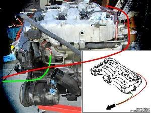
- Finally, there is one more vacuum line that must be run, as its hardline was also bypassed in this process. Originally running from the balance tube, through a hard line, and to the carbon canister (indicated in the red outline + green line), we have eliminated this hard line and must now run a vacuum line directly from the balance tube to the carbon canister (new line shown in red). This will be approximately 3 ft in 6mm vacuum hose.
- Because the balance tube is off now, run the line from the carbon canister port to the approximate location of the balance tube port and set it off to the side for now.
- There are actually two vacuum lines that run to the carbon canister--the line in question runs to the lower port in the pair of hardlines over by the carbon canister. If referring to our Vacuum Diagrams, this is the blue line that runs from the balance tube to the "to carbon canister" hard lines. The other line (shown in green on the vacuum diagram) will run to the nipple on the throttle body upon plenum re-installation.
- Go take a break! You're done.
Double Check
Just to make sure you've routed all the lines properly, refer to the Vacuum Diagrams page, and check your coolant lines against the diagram below.
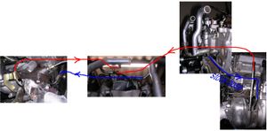
Note: This bypass practically only deals with the red hose; the blue hoses should remain pretty much the same. However, if you can access these, now is a good time to replace them.
NA Routing
On an NA, the simplest solution is to simply cap the water lines with rubber bypass caps. Since there are no turbochargers, removing the cooling lines to the throttle bodies obfuscates the cooling lines altogether.
