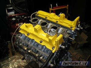
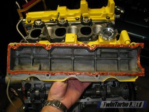
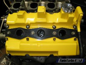
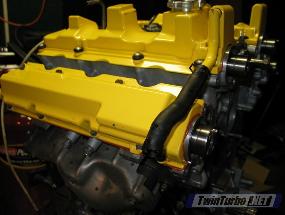
Valve Cover
The Valve Cover attaches to the top of the cylinder head and protects the camshafts, lifters, and indeed the entire valvetrain. They also serve to keep oil from escaping from the head, and in the case of the Z32, to allow positive crank case pressure to ventilate.
The Z32 uses four valve covers. One for the intake cam and one for the exhaust cam, on each head.
Images from TwinTurbo.NET and Aus300ZX.com.

Contents
Removal
Prerequisite: Remove the Intake Manifold.
Tools Needed
- Philips and flat-head screwdrivers.
- 10mm and 12mm sockets and ratchet.
- Assortment of U-Joints, wobble joints, and extensions.
- Long needle-nose pliers.
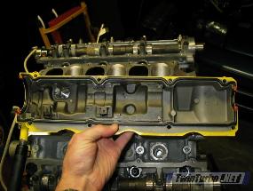
Intake Valve Covers
The two centers valve covers, which cover the intake cams, are very easily removed.
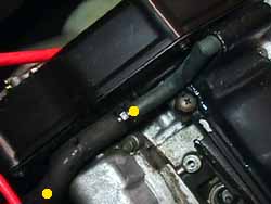
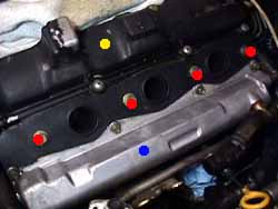
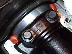
- Disconnect the PCV hoses (yellow dots on the clamps) that run from the valve covers to the accordion pipes. If these are old and brittle, now would be a great time to replace these with silicone versions.
- Remove the 4 x 12mm bolts (red dots) holding the spark plug guide down. Remove the guide, being careful not to lose the little rubber seals at the end.
- Remove the 8 philips-head screws on the valve cover.
- Be careful not to lose these screws or the little "spacers" underneath them.
- Lift straight up on the valve cover to remove it.
- Repeat for the opposite side valve cover.


Exhaust Valve Covers
- Disconnect the PCV hose at the rear of the driver's side intake valve cover and remove it. If it's too brittle to remove, you can leave it connected but loosen the clamp so the hose can slip off when you remove the valve cover.
- Now would be a good time to replace this hose with a silicone version.
- Remove the 4 x 12mm bolts (red dots) holding the spark plug guide down. Remove the guide, being careful not to lose the little rubber seals at the end.
- Remove the 2 x 10mm bolts securing the EGR pipe to the EGR valve near the back of the plenum (Main article: EGR Removal).
- Remove the 8 x 10mm bolts securing the valve cover to the cylinder head.
- For the driver's side, twist and loosen the bracket securing the oil dipstick tube to the valve cover.
- Lift straight away from the cylinder head to remove the valve cover.
- Repeat for the opposite side valve cover.
Installation
Tools Needed
- Philips and flat-head screwdrivers.
- 10mm socket and ratchet.
- Assortment of U-Joints, wobble joints, and extensions.
- Long needle-nose pliers.
Parts Needed
- Intake Valve Cover Gasket Set.
- Half-Circle Exhaust Valve Cover Seals (Solid versions are recommended).
- Liquid Gasket maker.
Intake Valve Covers
- Disconnect the VTC Solenoid harness connector.
- Remove the 2 x 10mm bolts securing the VTC solenoid to the back of the cylinder head.
- Remove the old liquid gasket from the VTC solenoid and cylinder head. Ensure that the gasket mating surfaces are both clean and free of debris.
- Apply a narrow bead of RTV across the bottom of the VTC solenoid.
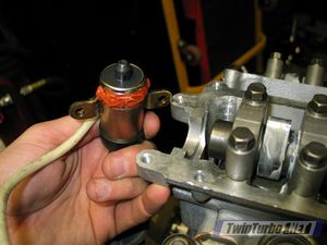
- Carefully place the VTC solenoid so that its plunger is lined up with the back of the cam and the bolt-holes are lined up. Hand-thread the bolts in.
- As per your gasket maker's instructions, wait any necessary amount of time for the bead to tack up, then snug the bolts down fully. Torque bolts to 12-18 lb-ft.
- Remove the old gasket from the valve cover (assuming it doesn't simply fall out). Ensure that the gasket mating surfaces are both clean and free of debris.
- Apply a small dab of RTV to the corners near the front of the intake cam.
- Lightly coat the new gasket with motor oil.
- Insert the new gasket into the groove on the valve cover until it's nice and snug.
- Place the valve cover over the cylinder head and hand-thread the philips screw heads in place. Don't forget the little rubber spacers!
- Progressively tighten the philips head screws in a spiral pattern (starting from the inner-most screws) to 0.7-2.2 lb-ft (which is basically reasonably snug).
- Re-install the spark plug tube guides, being careful to make sure the rubber seals line up properly. No torque setting is listed, but they should be reasonably snug, keeping in mind that the cylinder head is aluminum.
- If you're not doing the exhaust valve covers, go ahead and re-install the PCV hoses now.
- Repeat for the opposite side valve cover.


Exhaust Valve Covers
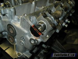
- Remove the half-circle (sometimes called "half moon" which annoys me because they're half-circle shapes, not half-crescent shapes >:( ) seals at the rear of the cylinder head. Remove the old liquid gasket material from this seal and the mating surface on the head. Make sure both surfaces are totally clean and free of debris.
- If you haven't done so before, now would be a good time to replace the half-circle seal as they tend to shrink over time. Even better, use solid aluminum versions available from your friendly neighborhood parts dealer.
- Apply a thin bead of liquid gasket to the underside of the new half-circle seal, and gently insert it into the cylinder head where it belongs.
- Remove the old liquid gasket material from the valve cover and head. Ensure that both mating surfaces are totally clean and free of debris.
- Apply a bead of liquid gasket material to the underside of the exhaust valve cover. There is a groove for this gasket.
- For the driver's side, make sure the oil dipstick tube bracket is up and out of the way--it likes to jump in between the valve cover and cylinder head.
- Place the valve cover straight onto the cylinder head, being extremely careful not to allow any RTV to rub onto the valvetrain components. If you mess this up, just take it off, clean off the material and try again.
- On the driver's side, set the oil dipstick tube bracket over the valve cover, lining up the bolt holes so the bolt secures down the bracket and valve cover.
- Hand-thread the 8 x 10mm bolts in.
- Working in a circular motion (starting from the inner-most bolts), tighten the bolts down to 4.6-6.1 lb-ft.
- Re-install the spark plug tube guides, being careful to make sure the rubber seals line up properly. No torque setting is listed, but they should be reasonably snug, keeping in mind that the cylinder head is aluminum.
- Re-install the PCV hoses to the intake valve covers.
- Repeat for the opposite side valve-cover.


