Intake Manifold Removal
Removal of the Intake Manifold (also called the plenum) is necessary or helpful to perform several jobs on the VG30DE(TT), such as:
- Fuel Injector Replacement (as an alternative to the Dremel Method).
- Valve Cover re-seal.
- PCV reroute/delete.
- Throttle Body Coolant line bypass/removal.
- EGR bypass/removal.
- Cylinder head work (replacement, lifter removal, cam replacement, etc).
The most common reason to remove the intake manifold is to replace one or more faulty fuel injectors, and other jobs are usually performed at the same time due to the amount of labor required to remove the intake manifold. While it can be done in less than an hour (especially after doing various deletes/bypasses), it involves removal of multiple engine technologies, from coilpacks and vacuum lines, to fuel lines and EGR tubes. This is often intimidating for owners, and is often considered to be a much harder job than many feel it actually is. If you're new at this, bag and label everything!. In any case, a handy guide with pictures makes everything easier!
Pictures and info from this article are a combination of those from NytWolf, those found on the Tech section of Aus300ZX, and various other sources (including my own noggin). A huge thanks goes out to the original photographers and writers for the work they put into making these writeups, which have saved headaches for hundreds of Z owners.
Contents
Recommended Parts
- Intake Manifold Gasket (upper plenum to lower plenum) (Part #14033-30P02). Required. This is a paper gasket that is destroyed upon removal and must be replaced. OEM Nissan is recommended (and is very cheap).
- Balance tube O-ring set (if they haven't been replaced yet).
Tools Needed
- 8mm, 10mm, 12mm, 12mm (deep) sockets.
- Ratcheting driver for sockets.
- Flex joint (U-Joint) and various extensions HIGHLY recommended.
- 8mm, 10mm, 14mm wrenches (stubby wrenches and ratcheting wrenches are also very helpful).
- 5mm Allen wrench.
- Long needle nose pliers.
- Philips & Flathead screwdrivers.
- Dental pick set is helpful for various electrical connectors.
- Hose removal pliers rock for this.
Procedure
Upper Components
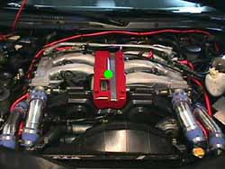
The image below will be used as supplemental reference for the following steps.

We'll start by concentrating the components on and around the top of the intake manifold.
- Relieve fuel pressure from the system (link).
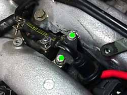
- Remove throttle cable cover (Item 3) (green dot; 4x5mm Allen bolts).
- Slightly loosen 14mm bolts holding the throttle cable and cruise control cable to the bracket on the upper plenum. You may have to remove some little bracket guides (10mm bolts) that bind the cables to the plenum. The cruise control can optionally be removed, but I've found you can just gently flex the cables out of the way. The wiper blades do a good job holding them down.
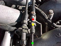
- Disconnect all vacuum lines attached to the balance tube (yellow dots pictured below). It may be helpful to label them--tape and a marker work well.
- Remove the 3x12mm nuts and 2x12mm bolts holding the balance tube to the plenum (green dots below).
- Remove the large vacuum lines that run to the brake booster and clutch booster (on M/T TT Models) (Items 6). Also remove the vacuum line from the front barb fitting (the one leading to the clutch booster on applicable models).
- There is a tube that runs from the driver's side accordion pipe to the IACV at the back of the plenum (Item 14). Remove the 10mm bolt securing it to the plenum. Loosen its hose clamps (at the accordion pipe and where it meets the IACV) and remove this pipe assembly.
- It may be necessary to remove the barb fittings for the clutch and brake boosters that attach to the plenum in order to remove this pipe.
- Loosen the hose clamp for the Air Regulator Hose at the back/center of the Balance Tube. Remove this hose.
- If you can't get this hose off, don't sweat it--you can pull away from it while removing the balance tube, which makes it much easier.
- Disconnect the fuel lines that go from the Fuel Dampener to the Fuel Rail, and from the Fuel Rail to the FPR (circled in red).
- Remove the bolts that hold the Fuel Dampener and Fuel Pressure Regulator to the plenum. (2x10mm for each).
- Remove the 3x10mm bolts that secure the upper fuel gallery to the plenum. Remove the fuel gallery.
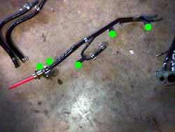
- I tend to leave the two main hoses (feed and return) connected to the fuel gallery and simply flex them and set the gallery off to the side. To be extra cautious, feel free to remove these hoses and the fuel gallery completely. Be aware that fuel can quickly damage paint, so keep this in mind when fiddling with the fuel gallery.
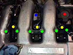
- Disconnect the electrical connectors for the six coilpacks (yellow dots below). Remove the coilpack wire guides (philips screw head, blue dot) and, if necessary, the oil cap (red dot).
- Remove the 12x12mm bolts (2 each; green dots below) that secure the coilpacks to the plenum. Remove the coil packs.
- Remove the injector connectors from each of the six fuel injectors. This is where your dental pics come in handy (if you have Phase 1 injectors).
- If you lose the little spring clips, don't worry. You can recover them once you get the plenum off, and many don't run them at all--a small dab of RTV on the flat (non-electrical) face of the component will help secure the connectors.
- Remove the connectors to the IACV components (more dental pick mayhem):
- AAC (Yellow connector)
- FICD (Blue connector)
- Air Regulator (Blue Connector)
- Disconnect the TPS (spring clip at the front, regular oval connector at the pigtail)
- Remove the two ground wires (1x10mm bolt each). One is near the rear passenger side of the plenum. The other is near the rear driver's side.
- Flex the wiring harness up and out of the way. I also tend to use the wiper blades to hug this to the windshield and keep it out of my face.
- Go take a break!


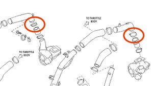
Intake Pipes
- Remove the throttle intake pipes. These are the two pipes that connect directly to the throttle bodies. Plug these pipes.
- TT Models: remove the front turbo outlets. These are the "outer" intake pipes that run from the turbo outlets to the intercoolers. Plug these pipes.
- TT Models: On each side of the plenum are "support brackets" that connect the intake manifold to the heads, and each have a 10mm bolt (blue dot) connecting the turbo outlets. Remove these two bolts. Also remove the two 12mm bolts (orange dots) securing this bracket to the plenum.
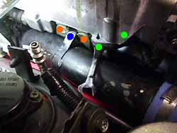
- TT Models: Grab a stubby screwdriver and loosen the upper hose clamp that secures the turbo outlet pipes to the rubber couplers on the turbochargers.
- TT Models: Remove the turbo outlet pipes. Plug these openings.


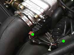
Driver's Side
Let's concentrate on some components on the driver's side for a bit.

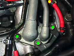
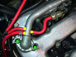
- Loose and slide-off the hose clamp for the PCV hose (Item 1). If you plan on replacing these hoses, cut that shit off.
- Remove the throttle body coolant lines (Items 2 and 3). If you are doing the coolant line bypass (highly recommended), save yourself some trouble and just cut these hoses.
- Remove the bolts (2x10mm) securing the EGR feed line to the plenum underside.
- Remember earlier when I said to plug the pipes you removed? Make sure it's done! These EGR bolts are notorious for falling into the turbo inlet pipe.
- These are a total bitch to remove, but play around with different combinations of extensions, swivel joints/flex joints, stubby wrenches, etc, and find what works for you.
Passenger Side
Moving over to the passenger side...

- Remove the throttle body coolant line (not labeled above, but it's in the same position as on the driver's side).
- If you're doing the coolant line bypass (highly recommended), just save yourself the grief and cut these off.
- Loosen the hose clamp for the PCV hose (Item 8). If you're replacing the PCV hose, just cut the old one.
- Remove the rear coolant line (on turbo models) (item 9).
- Remove the EGR tube (item 7).
Rear Side

- Remove the hose clamp for the rear driver's side coolant line (Item 10).
- Remove the hose clamp for the rear passenger's side coolant line (item 11).
- Remove these two lines. If you're doing the coolant line bypass, just cut them.
- Disconnect the EGR vacuum line (item 12).
Upper Plenum
- Remove the main upper plenum bolts.
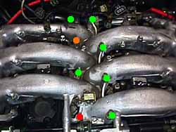
- Regular bolts (green dots) are all the same. Red dot is the short one, and orange dot is the hex-head one (which doubles as a mounting point for the throttle cable cover).
- Carefully lift the plenum up directly away from the engine. If you left the PCV hoses connected, allow the rear to tip back towards the engine.
- Making sure there are no snags, electrical connectors, hoses, etc still hanging on, pull the plenum towards the front of the engine. If you left the PCV hoses connected, pull the plenum away to help pull the PCV hoses off the PCV valves on the plenum. It helps to have a partner with this!
- When handling the intake manifold, be careful not to damage the TPS or IACV.
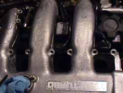
- Plug the lower intake manifold ports (6).
- Go take a break!


Post-Removal Jobs
There are a few different jobs that can be completed when the intake manifold has been removed. Now that it's done, check out the guides for some of these jobs:
- Coolant Line Bypass
- EGR Bypass/Removal
- PCV Reroute or Delete
- Fuel Injector Replacement
- Valve Cover Re-seal
At the very least, it is highly recommended that you complete the coolant line bypass. This makes future plenum pulls much, much easier, in addition to eliminating multiple points for potential coolant leaks.
Re-installation
Aside from any deletes/bypasses completed, installation of the plenum is the reverse of the removal. Be careful when installing the new plenum gasket as it's paper and easily damaged, and ensure that the gasket mating surfaces are clean and totally flat.
The torque specs needed for reinstallation are as follows:
- Plenum bolts: 12-15 lb-ft (do in a spiral pattern starting from the center).
- Side braces: Approx 6-8 lb-ft.
- Balance tube nuts and bolts: 12-15 lb-ft.
- EGR bolts: 6.2-8 lb-ft.